
Hello, everybody! We’ll continue with our series on the Nikon I/M/S and I’ll show you the techniques that I use when working on these cameras. Part 1 was all about removing the external parts and how to work on the rangefinder. In this part, I will show you the more difficult scenarios when repairing this camera. While this is Nikon’s first 35mm camera it sure is complicated enough to provide an experienced repairman with a challenge. This is not a camera for the beginner to play with, buy a cheap FED to play around first before you try your hands on this. The Nikon S is much too precious to be a practice camera! It’s important to note that these are great cameras to use on a daily basis for fun and they’re going to work for decades after a good overhaul so make sure that you keep it working.
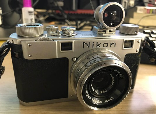 I love my Nikon S. They’re really reliable cameras and I hope that people will appreciate them more instead of being merely collectible items. With proper love and maintenance, these cameras will last for decades after a good overhaul.
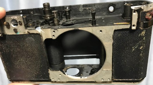
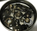
 This is the task ahead of you. See how dirty it is? The shiny grime you see here is flushed-out oil. I use Zippo oil for this job and I was very careful not to make the curtains and the ribbons wet or else their glue might fail and I will be in trouble!
Before you continue you will want to ask yourself this question – am I ready for this? This is not going to be easy and you will need to have some specialized tools like small drivers and spanners in order to remove some parts safely. I will show you how to dismantle this camera down to its basic parts (almost) completely and I will advise you to take out your camera phone and snap as many pictures as possible for reference. If you have a digital micrometer, that will help you a lot in determining tolerances so you will know if you got things right provided that the last guy who worked on your camera didn’t mess things up and throw the original tolerances off. Let’s now begin with part 2!
Disassembly (Light Shields & Covers):
The light shields are easy to remove but you will have to remove some parts in order for you to reach well inside the camera to remove their screws. While most are pretty direct, there are a few light shields that will require more effort to remove. Here in this section, I will show you how to remove the light shields and other related parts. I’ll have to warn you first before you do this because you are entering the point-of-no-return because once you begin you will have to finish it or else you will just be doing a half-assed job.
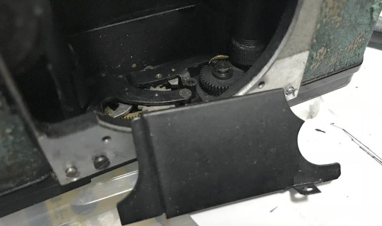
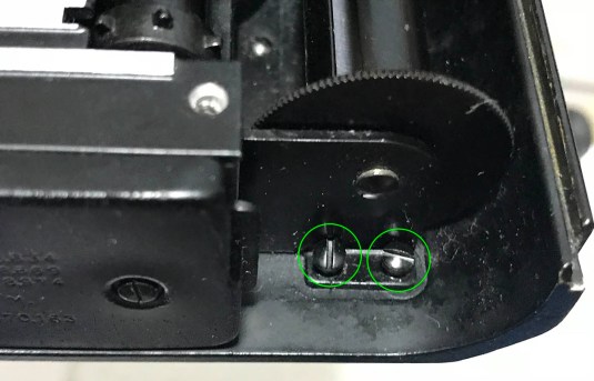
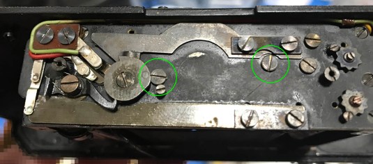
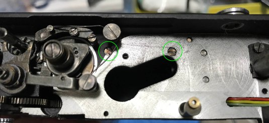 To remove the top light shield / baffle, remove these 2 screws. There are some parts that’s in the way so be careful when removing these.
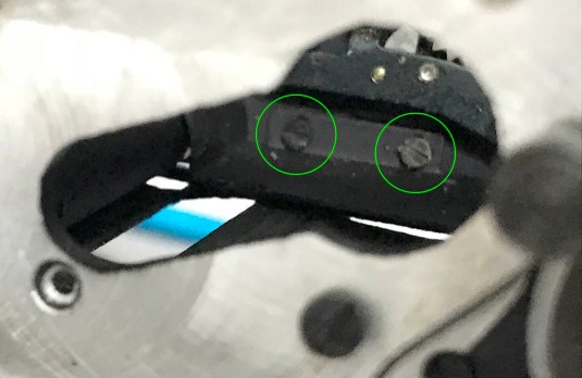
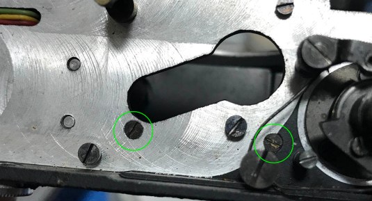 Here’s a closer view of the screws.
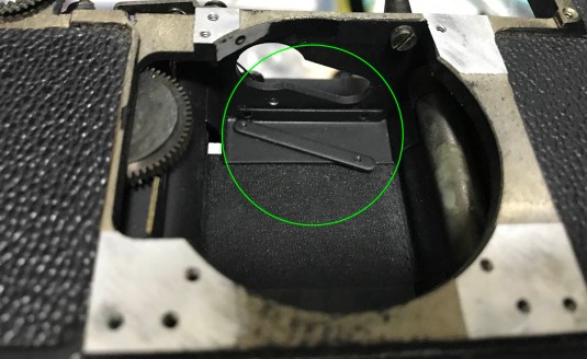 Once the 2 screws are gone, you can remove this part and the top baffle can be removed easily but be careful that the baffle doesn’t scratch the cloth curtain.
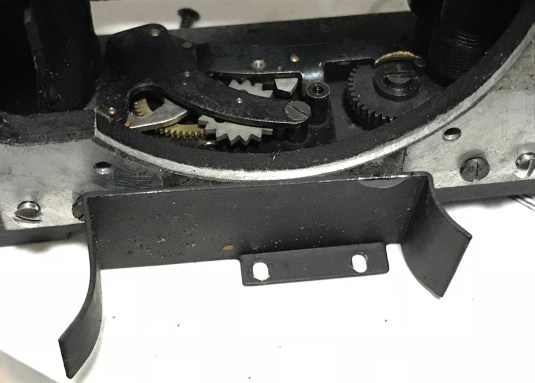
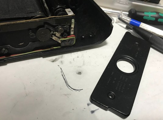
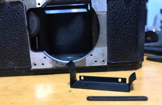 This is how the baffle looks like. The flanges are curved and they wrap-around the drums of the curtains. If any of these were to be warped and touch the drums then you run the risk of these scratching the cloth and causing the shutter to fire inconsistently. Scratching the curtains is never a good idea and it can lead to a torn curtain/s.
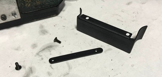 Here’s a closer look of the back part of the baffle. The part with the screw holes can warp easily so you want to handle it with care when putting this thing back. It can be adjusted somehow but not by much.
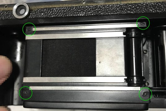 To remove the aperture gate, simply remove these 4 screws. Be careful while you remove it because the guide rails were casted to it as a single part. These rails should remain flat.
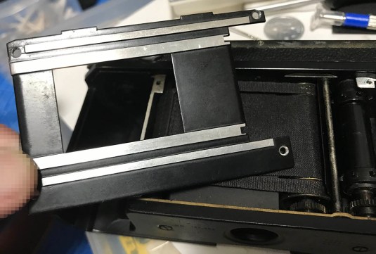 This is how it looks like when you remove it. Do note that there are 2 small tabs on mine, your may not have this or may look different so please pay attention. We have to remove this in order to access the other screws to remove the rest of the light shields.
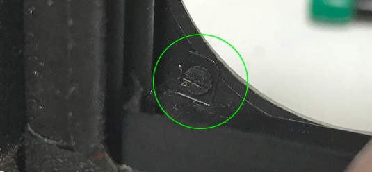 With the aperture gate casting gone you can now access more screws. Begin by removing this one to remove the lower baffle.
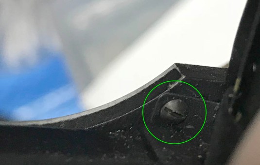 Here’s another one that you should remove but this one is for the baffle to the right and not for the lower baffle.
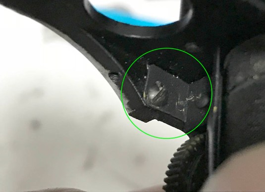 This is the last screw for the right-side baffle. Now, you may be asking why we’re getting rid of the screws for this baffle when we want to remove the one at the bottom. This had to be done because if this baffle is loose then we can remove the lower one much easier.
 Here’s the lower baffle. Notice that it only has 1 tab for a screw. If you have an older one then this part will be absent. On cameras older than the Nikon M/S, the lower baffle had not been implemented yet so in place of it Nikon used a different design as you’ll see in a bit before the end of this section.
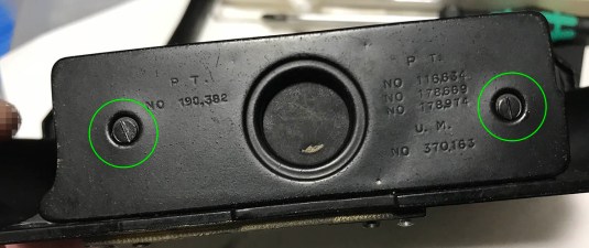
 At this point, it should be easy for you to remove the lower-rear baffle by accessing the 2 screws from this opening. It can be tricky to get to these with a shorter driver.
 Here it is, notice that the screw holes are elongated like the ones at the top baffle. This is adjustable just like the top light shield so if you suspect that the baffles are touching the curtains then just move these forward a bit.
 You can finally remove the right-side baffle because nothing is obstructing it.
 You can remove the spool by unscrewing these. These screws secure the holding bracket for the spool. If I’m not mistaken, there are at least 2 types of brackets that I have seen so if yours look different from what I have here in this picture then study it first before you remove it so you won’t damage it.
 To remove the bottom cover, unscrew these 2 screws and be careful not to strip these. It’s nice to see the beautiful engravings, these cameras hark back to a different era.
 The cover should come-off easily once the screws are gone. Keep it safe and clean all the dirt that you can find underneath it.
 There’s another light shield at the back and it’s being held by these 2 screws. These won’t be possible to remove at this point because the sprocket is in the way. You can only get it off after the sprocket is gone so stay until the end of this article to see how it’s done.
That’s all for the main light shields, I will show you how to remove the final baffle in the next section. This and the next section should actually be just one part but it will make it too long and I’ll get bored writing everything. Things will get more and more difficult as you proceed so I am warning you in advance.
Disassembly (Internal Parts):
This section is probably the most time-consuming part of this article, taking things apart is easy but putting them all back properly will test your skill and patience. I will remind you to take as many notes and pictures as possible before every step you make. All of the references you take will be helpful to you later and will prevent you from getting stucked and save you hours of frustration. Obviously, this is where many people get stuck.
 To remove the slow governor or retarder, remove these 2 screws. Be careful not to drop the slow governor when the screws are gone.
 Pick the slow governor with your fingers and be careful that it won’t snag on something. You may end up bending the claw or other important parts.
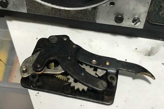
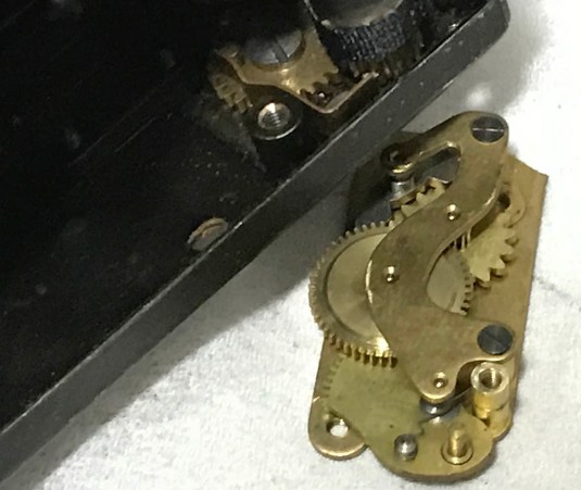
 Ok, here’s what I promised a while ago. What you’re seeing here is the slow governor of an early Nikon M/S. The mechanism is encased in its own housing unlike the later ones, it is not completely covered with a light shield. Nikon knew this so they improved it but it’s just a stop-gap and the light leak problem will never be fully-resolved until the Nikon S2. Nikon admitted this on their website outlining the history of Nikon cameras. This is their first camera design so who can blame them?
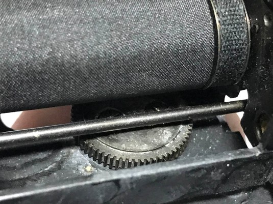
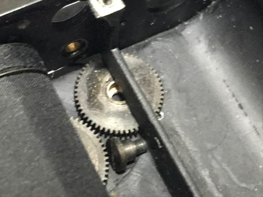
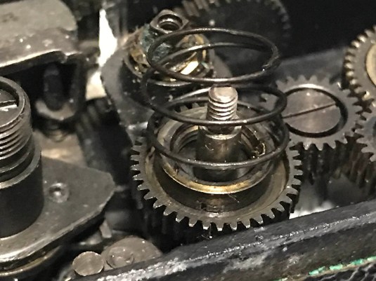 Don’t lose this spring. This spring pushes the cog underneath it so that it engages the ring and crown gear underneath which in turn drive the sprocket.
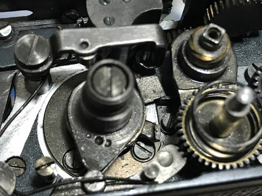
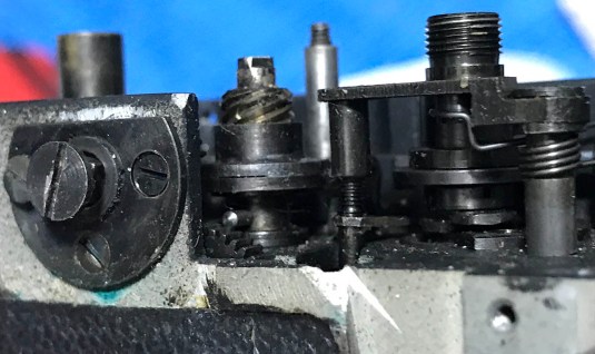
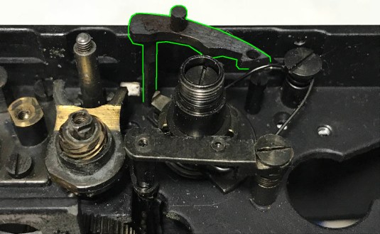
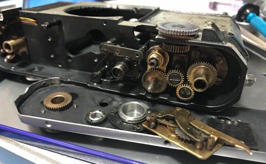
Study the mechanism very well and see how it works before you begin dismantling it. It’s not that complicated so you’ll understand how it works easily. Basically, that cam shaped like a tear-drop spins when you’re taking an exposure. That thing is driven by one of the curtain’s drums so it’s in-sync with it. That small stud or pawl you see here in the picture that is touching the tip of the tear-drop cam gets kicked bt the cam as it spins. How early or late the cam strikes this will determine the time that the aperture stays open. When it is kicked, it pushes the 2nd curtain lever that is connected to it and that will release the 2nd curtain and that will close the shutter. This is how the higher speeds are regulated. I want you to look at the rectangular thing to the right of the cam. That thing is connected to a long shaft that winds the slow governor. When you select the slower speeds, this tab will come closer and closer to the cam and get in the way of the cam’s rotation, When it gets kicked by the cam, it will stop the cam and cause the cam to travel slower until the slow governor releases the shutter and then the shutter closes. How slow that’s going to be will depend on how low or high this tab is positioned. Here in this picture, that tab is resting on a stop. This is the position when you set it to time (T). The tab will remain like this until you change the shutter speed and dislodge it from this position, allowing this to move again and closing the shutter. Remember this very well, when putting the top back you will want this to be in this configuration (T) so that the slow speed lever or arm is not going to get in the way of the slow speed selector cam at the top plate. I know this sounds confusing for now but this will make sense when you work on the camera.
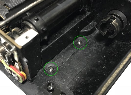
 If you wish to clean the advance mechanism gear train you can remove these screws and clean the cogs as thoroughly as you can with a brush and some chemicals. How smooth it operates will depend on how clean it is.
 This is how it looks like after some brushing and flushing with solvents. If you are scared of taking this apart then this is probably going to work just as well but it’s not going to be good enough for people like me.
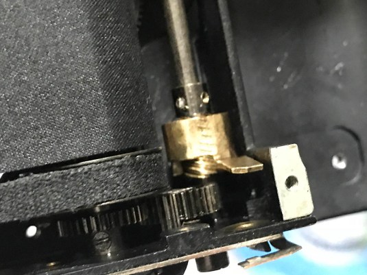
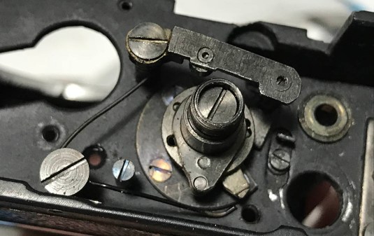
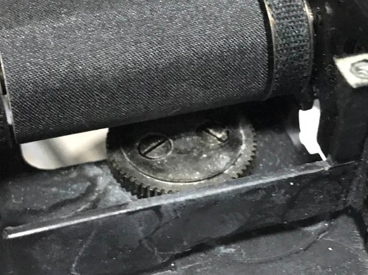
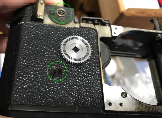 At this point, you will also want to clean the focusing wheel and remove the cog behind it to better access some of the parts surrounding it. These can get corroded and stuck with old lubrication and the only solution is to clean them thoroughly. To remove the focusing wheel, simply unscrew the fastener securing it. Note that the wheel’s center has a square profile. It doesn’t matter how it’s reinstalled so long as it stays flat.
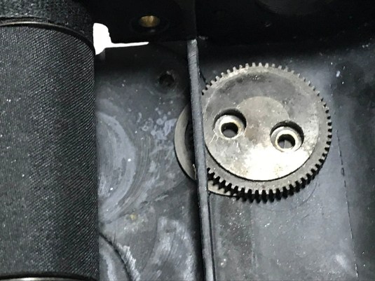
 The plate holding the serrated focusing wheel can be removed by unscrewing 3 screws. It is a good idea to clean the hole at the center with a Q-tip so it’s smooth.
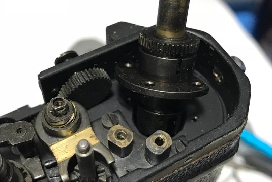
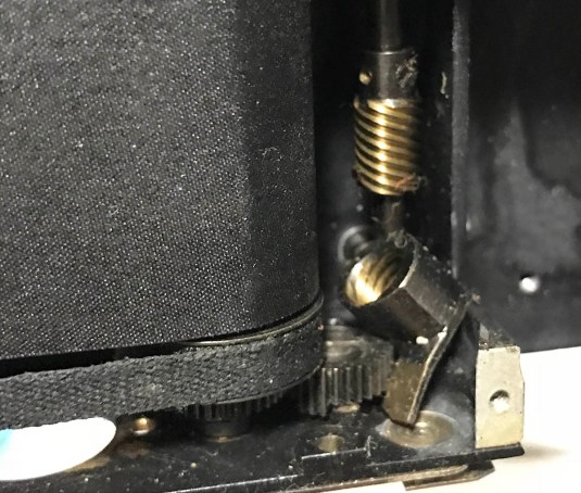
Before we move to the next step, I would like you to take as many pictures and notes for this part of the camera because we’re going to dismantle this soon. See that mini-helicoid at the center of the picture? You should take as many pictures of that if you can because you will have to put that back the way it was and pictures and notes are all you’re going to have as reference. Take note of the position and orientation of the parts in relation to its surroundings.
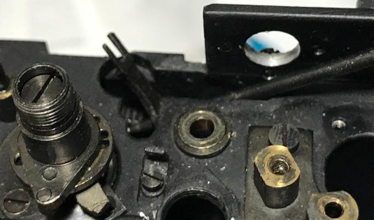
 Going back to the advance gear train, you can remove the spigot from the chassis casting by removing 3 screws. Note that the other 2 cogs were removed earlier by me. When you put these cogs back, be sure that they’re reinstalled back to their proper holes because it is best that they mesh together the same way as they did before you dismantle them.
This spigot was connected to the advance knob and that’s the main thing that turns when you advance your film. If this wasn’t cleaned properly then advancing the film won’t feel as effortless as you would like it to be.
Notice that I removed the spring and the main cog for the film advance sprocket. What is seen here is the yoke. The yoke has its own helicoid so if you turn the A / R lever towards R this will push the cog up so it disengages the crown gear underneath it. Turn the lever towards A and the spring atop the cog will push it down so the cog will catch the teeth of the crown gear so it can turn the film advance sprocket and charge the shutter. Notice a strip of polished brass on the yoke? That is where the cog rests so it has to be smooth and clean for it to move properly. If this got damaged then you will have a problem.
 At this point, we can also remove the rear curtain lever assembly. It’s being secured by a spring that pushes is down. Be careful while you remove this because you don’t want to accidentally tension or weaken the spring. Alternatively, you can just remove the screw at the top of the spring and safely remove it but that’s going to be more work to put back. You can do anything you want so long as you don’t damage or warp the spring. If this is a little bent or tensioned the wrong way then it’s going to affect your shutter and you won’t get consistent shutter speeds or the rear curtain won’t work at all. Once the spring is out, you can simply pull the rod of the rear curtain lever and it should come-off easily.
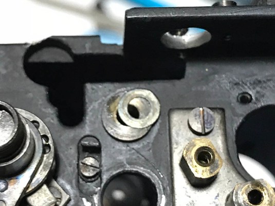
 This set screw secures the collar that it’s attached to. The collar is used to adjust how high or low the fork for the spool is. It’s important that the film is parallel to the aperture gate and this is one way to ensure that they’re level with each other.
 The spigot can be taken apart by removing this screw. You will have to grab the cog at the other end with your fingers to prevent it from turning as you unscrew this.
 Once the screw is gone the whole thing comes apart. Clean it as good as you can and then leave the whole thing in solvent to help dissolve any left-over gunk.
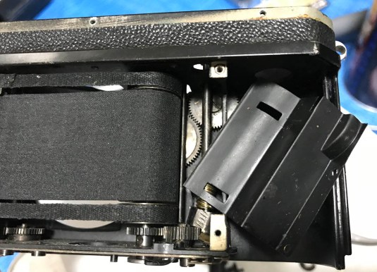
 OK, let’s side-track a little bit and remove some other parts before we remove the yoke, it is important that we remove these first in order to get it out as easily as possible. Remove this screw so we can free the rod for the sprocket’s lower part. It’s stuck to this cog so it’s going to turn the gear train at the base of the camera, this will charge the shutter as you can see from this picture. Never mess around with anything in the shutter assembly yet.
 Here’s another one. The screw makes sure that the film sprocket turns when you turn the dial to advance your frame.
 Once those 2 screws are gone you can pull the plunger rod out from the chassis. This rod will depress along with the shutter button and it will spring back up because the bottom is resting on a long flat spring.
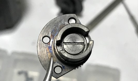
 Take a look at the rod. There’s a depression near the lower tip, that’s where you will have to sink the screw for the lower shutter charging cog. There is a slit on the other end so it’s possible for the screw of the sprocket to slide up-and-down within it. If I’m not mistaken, the sprocket is being held in-place by another part and that’s the crown gear. You’ll need a specialized tool to remove the crown in the form of a rubber tool. This rubber tool will grip it without damaging it and it will allow you to safely unscrew it off. Once that is off, you can safely remove the sprocket.
 The sprocket is finally gone! ou can finally remove the shield covering the deepest parts of the camera. This is the only way you can get to this part for the Nikon S because it does not have a convenient access panel at the front like the later Nikon rangefinder models.
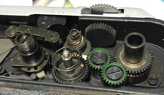
 These gears are used to focus the helicoid for the lens and are connected to the focusing wheel as a single mechanism. You cannot remove these safely for now because there are many things obstructing the way. I will show you how to remove these safely.
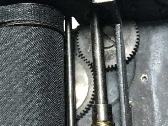
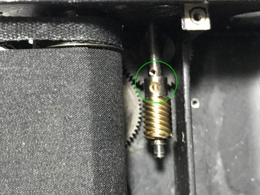
 Check this out very well. This is what’s going to keep the lower advance cog down when it’s set to A and and pull it up to disengage the advance gear train when set to R. This will fire the shutter when it’s cocked when you turn the A / R lever from A to R. Just like what you saw in the yoke at the other end, it also has its own mini-helicoid. Study it carefully and take as many notes and measurements as possible. Please do not turn this yet, this is connected to the other mini-helicoid on top and turning this will affect the position of the other one. I will show you how to remove this properly in the next steps.
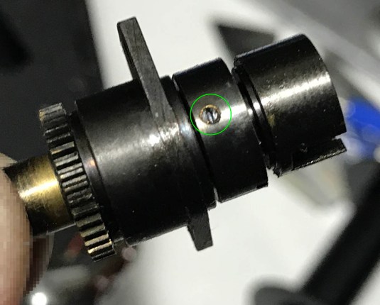
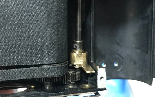
 To remove it, look for a small screw and remove it but first make some scratches on the surface of the metal so you know which side the head of the screw was attached and how it was oriented before you removed it. This screw acts like a small pin.
 Now that the screw is gone, you can freely rotate the male helicoid but make sure that its rod remains as static as possible so you won’t affect the other helicoid at the other end. It will separate from the female helicoid as you turn it away. Like any helicoid, don’t forget to mark where they separated because this is also where they should mesh. Clean this as best as you can because there is a big chance that this was never opened since this thing was made. Be careful not to lose any washer or bushing that you find here.
 You can now pull the rod from above along with the yoke attached to it. You’ll also need to separate the mini-helicoid from the rod in order for you to pull the rod away from the chassis.
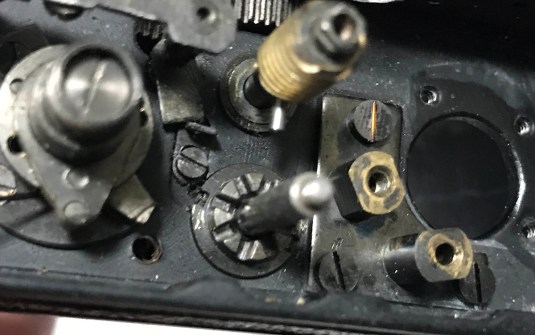 Sorry for jumping to another part of the camera awhile back but it’s important that need to remove as many obstructions as possible and clean them while we’re at it. Going back to the advance mechanism at the top of the camera, you can remove the yoke by turning it until it separates from its male helicoid. Again, make sure you make marks and scratch where they separated just like what you did to the lower mini-helicoid. This image shows how it looks like with the yoke gone and the rod put back in-place temporarily. I also put the crown back so I won’t lose it.
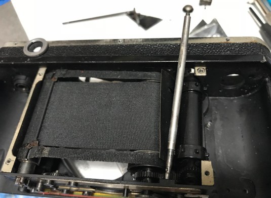
 Ok, time to work on the focusing gear train but you can’t access this properly because the shaft of the retarder is in the way. See the decades-old filth? They have more than 65-70 years to get to this state, that’s disgusting!
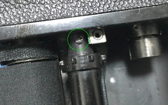
 To remove the rod, remove the screw at the top of the lever.
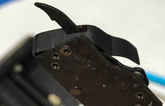
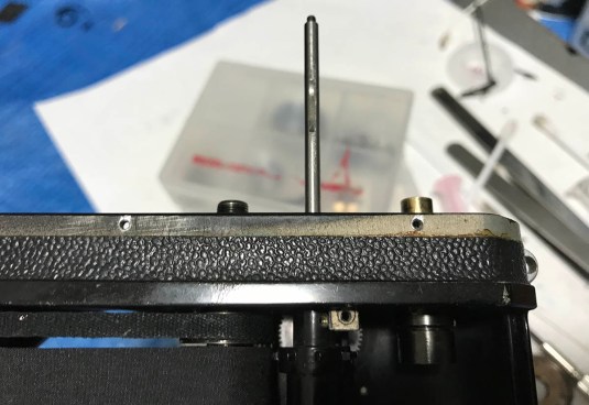
 The shaft can now be pulled from the chassis but be careful not to bend the little claws at the end of it. These claws charge the slow governor and it won’t charge it properly if it’s a bit bent out-of-shape. This is a delicate part so please be careful when handling it.
 Be careful not to lose any washers here. I found one here and there may be more of them in you camera depending on how far the measurement is from the factory tolerance.
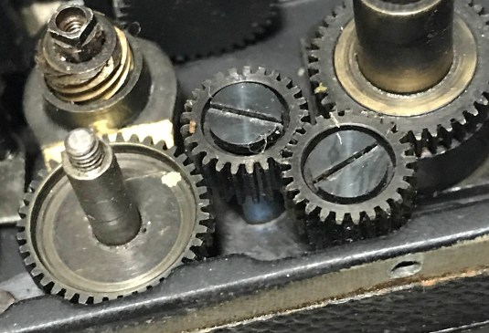
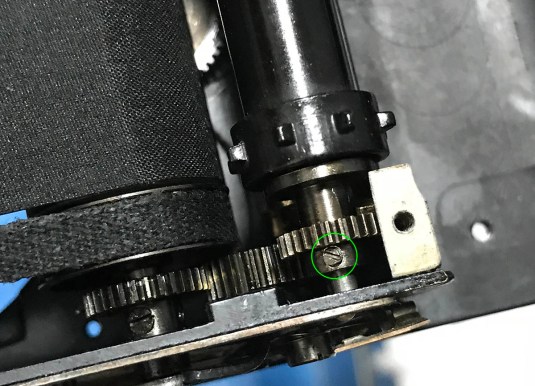
 You can finally remove the screw securing this cog. It can be tight so you’ll need to have a set of nimble fingers to remove this.
 Here is another cog. This is the trickiest one to remove amongst the two since half of it is under the rear curtain drum. The curtains for the drum has been replaced recently and I don’t want to damage it so this gets a bit complicated. I can completely dismantle it down to a bare hull but that would not make any sense.
 I carefully removed both screws with custom drivers that I modified for this kind of job. I was very careful not to damage the curtain in any way. It’s a great idea to cover it with a sliver of cardboard like a business card in order to protect the curtain from harm.
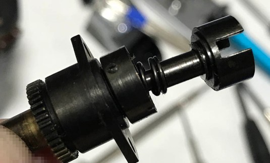
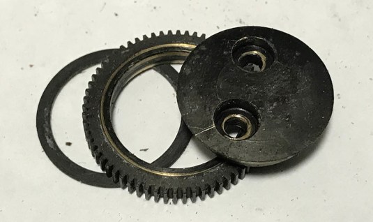 This is how the whole assembly looks like. It comes in 3 pieces and you will have to clean them all very well and polish the inner surface so it will give you super-smooth focusing action each time you turn the focusing wheel. Mine is feather-light after the overhaul.
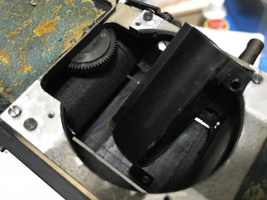
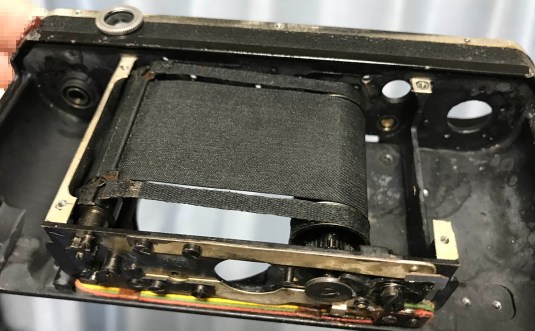
 This is how things look like by the time you reach this step, a nearly-empty hull with just the shutter assembly intact. There was no point in my removing it so I left it there. I was very careful cleaning it because I don’t want to damage the curtains as much as possible. Damaging it will mean that I will have to replace it and that’s going to take more time.
 Here it is, clean everything as best as you can. If your curtains are bad then it’s also time to scrape everything away but before doing that, wait for the next part where I will show you how to change the shutter of a Nikon S so you won’t mess it up.
That’s all for this section. In most cases, you will not have the need to dismantle the parts of the shutter assembly. I have repaired several cameras of this type and I have yet to get this thing apart to clean it. It will also be difficult to put it back again without a custom jig for positioning the drums. If ever I had the need to do this I’ll update this article and add some more steps and explain everything to you in detail.
Conclusion:
We’re here at the end of part 2. While this part has been reasonably lenghty, we have just tackled removing the internatl parts. This just shows how complicated part 2 is since the internal mechanisms are involved. Putting everything back will take more time and you will have to clean every part as well before you do it. Cleaning involves scrubbing all the parts with a small brush and solvent. If you have an ultrasonic cleaner then that is going to be best but you will need to dismantle everything in order for the cleaner to work in a really effective manner. Since I don’t have an ultrasonic cleaner available to me now, I’m going to show you an alternative way to clean the parts properly with chemicals. Before I proceed, I will make a disclaimer that I shall not be responsible for any harm to you and your equipment by following my method.
My method for removing corrosion on metal parts is to use citric acid. Make a solution so you can pickle your metal parts for a couple of minutes, it usually takes about an hour or so depending on the strength of your solution. I prefer a weaker solution so I can control or regulate how much the acid is eating away on the metal. Be careful when doing this, it will be strong enough to thin your parts if you’re not careful and dipped the parts for too long. Another problem is that the acid will eat the dark patina that Nikon applied to their camera parts. This patina makes the brass less prone to corrosion and also keep it dull so it’s less-likely to reflect any light. This solution can be bought here in Japan as “Blackie“, I know it sounds racists to some people but I don’t really care since race has nothing to do with it. Unfortunately for me, I don’t have any of this thing at-hand when I was cleaning my camera so I skipped this process. I want to warn you that using an ultrasonic cleaner will also remove this patina if you’re not careful with which solution you’re using and if you put this thing in the cleaner for too long. Having said all this, you’ll want a container that’s made out of plastic so the citric acid won’t corrode it. Disposing the acid is simple, I just pour it onto my toilet and let the acid clean the stain! Earth-warriors, don’t get angry at me for saying this because citric acid is just that – citric acid. The solution is benign, it’s so safe that you can use your hand to handle it and people use it to clean-away stains and grime from crockery. In fact, the chemistry we use to develop film is even more harmful to the environment.


Here’s how it looks like after about 45 minutes in the solution. Notice that the patina has been all but stripped and we now see the bare brass that’s hiding underneath it. You will need to brush this properly to clean it the parts that were left untouched. Before you put it back, make sure to clean it very well in running water just to make sure all of the acid is gone or else it will continue to eat the brass. After rinsing it, scrub it with soap and do another round of rinsing and soak it in alcohol to get rid of any residue. This sound like a lot of work but it’s not. This is one of the tricks for repairing watches that I have adapted for camera repair.
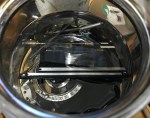
 The slow governor has been cleaned very well and I applied some fine oil at the pivots of the escapement. You won’t need any oil on the other parts because it will end up as grime after many years and that’s not going to be good. To be frank, these things were designed to function almost bone-dry. Brass is considered to be a “self-lubricating” alloy and that is enough to make this thing run properly without much oil. If you are wondering why this looks different, I disassembled it a bit to clean the escapement properly just to make sure that no acid residues are left. Don’t do this if you’re not familiar with this kind of work, it is never recommended to dismantle retarders.
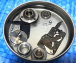
Here are some of the other parts fermenting in various solvents. Some grime will react to non-polar solvents while some won’t and this is just my way of making sure that I get rid of as much grime as possible. If any of the paint got stripped, just repaint them while the parts can be painted individually. Read my article on how I repaint letterings on cameras and lenses to give yourself some tips on how to do this properly.
 Here’s everything after all that work. See how beautiful it is? I lubricated all of the pivots with fine watch oil and applied grease to the teeth, shaft and bushings of all cogs or parts that operate with the power from your fingers. This includes the rewind mechanism, the film advance gear train, yoke, slow-speed selector and similar parts. Almost all parts that move automatically when you make an exposure was lubricated with a small amount of oil and some were left dry such as the teeth of their gears. You don’t want to apply lots of oil because it will spatter and spread as you use it and that will create a bigger problem for you and you’ll have no choice but to clean everything again, do you want to do that?
For people who have a Nikon S with working shutters, this is probably as far as you want to go. There’s no merit in going any further and I will show you how to adjust the shutter in part 3. If you’re unfortunate (most likely) to have a camera with bad shutter curtains, I will show you how to replace the curtains next time so please come back to see how that is done. It sounds daunting but it’s simpler than it sounds, I will even say that it is easier than the work involved in changing the shutters of the Nicca 3s because the Nikon S has a removable back and the rear casting comes-off just like on the Contax 2. Now you know why I consider the Nikon I/M/S to be the superior design overall. See you guys again next time and please share my work if you enjoyed this series. You can also support the blog by making a small donation to help with the upkeep like hosting, etc. Thanks again, Ric.
Help Support this Blog:
Maintaining this blog requires money to operate. If you think that this site has helped you or you want to show your support by helping with the upkeep of this site, you can simple make a small donation to my paypal.com account (richardHaw888@gmail.com). Money is not my prime motivation for this blog and I believe that I have enough to run this but you can help me make this site (and the companion facebook page) grow.
Leave me some tip?
Thank you very much for your continued support!
$2.00
Helping support this site will ensure that this will be kept going as long as I have the time and energy for this. I would appreciate it if you just leave out your name or details like your country and other information so that the donations will totally be anonymous it is at all possible. This is a labor of love and I intend to keep it that way for as long as I can. Ric.

Jul 16, 2018 @ 15:24:29
very very interesting trip inside “the S” , many thanks !
(I cant’t wait for the part 3… so I’m gonna corrupt you with a burger ^^)
Jul 16, 2018 @ 15:43:16
Thanks for the burger! I’m going to take a break this week on the S because it takes time to prepare so maybe next week! Ric
Aug 23, 2022 @ 08:19:40
Please could someone tell me where to repair a Panasonic Lumix FZ150 camera that won’t turn on. I have replaced the battery, but it still does not work. Please could someone help. I am due to take a trip on September 17th and don’t have the skill to shop again for a new camera. I like this one.
Jul 07, 2023 @ 03:37:38
Great tutorial! However I DO NOT recommend using anything on the slow-speed governor. I attempted to use citric acid for around 45 minutes, and all of the parts and gears to it were very very heavily corroded from it. Most of the gears fell out along with the springs. I have no idea how to put everything back together, and I attempted to purchase an actual factory service manual yet it gives no diagram or description of the mechanism. Sadly I believe my Nikon S is now lost unless there is a way I can use it with just the high shutter speed dial 😦