
Hello, everybody! We are going to continue with our Contax 2/3 repair series with part 2! In part 1, we tackled how to remove the covers and outer castings of the camera so that we can access the inner mechanisms and correct any problems with the shutter or any of the inner workings of the camera. This part is going to be more extensive as we work on the shutter and rangefinder of the camera. You’ll need to be an experienced repairer at the least before you tackle this part because this is complicated work. Remember what I said in part 1, this article is just for you entertainment and education. If your Contax 2 is needing repair, please send it to a competent repairman. The repair of the Contax series of rangefinders isn’t an easy task but it’s not impossible or overly-difficult as some would make it appear. Any competent repairman will be able to repair this. You can check out Hayata Camera here in Tokyo if you want. However, they don’t speak English fluently so if you need to send your camera there for repairs I can help you do that for a small fee. It is mostly for my transportation and time so I guess it’s reasonable.
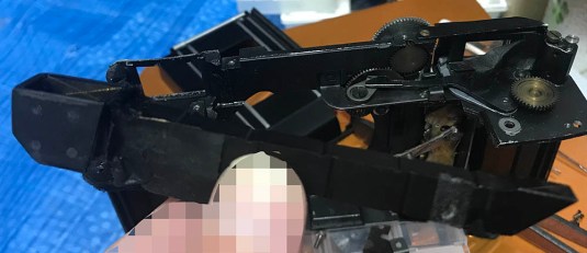
 This is the sort of thing that we will be looking at in this article. We will begin opening its internals and look deep into the camera to diagnose its troubles. This is delicate work so I will highly suggest that you prepare yourself and your workspace before you begin this.
We will try and see what’s wrong with this camera. It’s not really difficult to get this back to how it was before unless somebody worked on it before and messed everything up. It’s a nightmare working with such cameras and there are instances where a camera will not be restored to a proper working state just because the damage done to it by the previous guy is too much. You can invest a lot of time testing it all you want but that’s hardly wise and is going to cost you money in the form of lost time. Is it worth it? Yes, if you have all the time in the world or just sitting around in your house fermenting your testicles! That is not the case for most of us so if something like this happens and you are sure that this was tampered beyond-repair then only a transplant will be cost effective.
The Contax 2/3’s mechanism has more things in common to a watch than many pre-war cameras and it’s really a mechanical work-of-art. Having said that, this is a very delicate mechanism and small particles and corrosion is usually enough to cause the shutter and its escapements to work unreliably or fail. This will manifest as inconsistent speeds and timings to name a few examples. To complicate things, the shutter is not only clockwork but it also has ribbons that rely on friction to make the shutter work. Replacing these can be a problem because you will need ribbons that are of the same material and size. If it’s off by a few tenths of a mm then the shutter will not perform as good. The good news is that there are replacements that are close to the original material and I will show some to you in the coming part when we tackle this subject.
I am by no means an expert on this, I am merely chronicling my experience and sharing it to you. I humbly ask for the experts to please check and correct any mistakes here so I can fix it as soon as possible. If we don’t pass our knowledge then nobody will benefit or be helped by it when it’s time for us to go. I see this happen many times in the world of martial arts and I do not wish to see this happen here in camera repair. Please pass on the torch and keep the flame burning!
To help you navigate, here’s the link to the whole series:
Let’s now begin with part 2 and I hope that you’re prepared for this.
Before We Begin:
If this is the first attempt at opening a lens then I suggest that you read my previous posts regarding screws & drivers, grease and other things. Also read regarding the tools that you will need in order to fix your Nikkors.
I highly suggest that you read these primers before you begin (for beginners):
- Essential tools
- Best practices 1
- Best practices 2
- Best practices 3
- Ai conversion
- Working with Helicoids
Reading these primers should lessen the chance of ruining your lens if you are a beginner. Also before opening up any lens, always look for other people who have done so in Youtube and the internet. Information is scarce, vague and scattered (that is why I started this) but you can still find some information if you search carefully.
I highly recommend that you also read my working with helicoids post because this is very important and getting it wrong can ruin your day. If I can force you to read this, I would. It is that important!
For more advanced topics, you can read my fungus removal post as a start. This post has a lot of useful information here and there and it will be beneficial for you to read this.
Disassembly (Shutter):
Now that we have removed all of the external covers (in part 1), we are now free to open the camera even further and remove the shutter crate from the body casting. The shutter assembly can be removed as a single unit and that makes things a lot easier for fixing the shutter and its troubles since everything is accessible. Before we do that, we will need to remove a few things so we can extract the shutter crate. Remember, everything must be done in the correct order and must be put back in the same order in reverse.
Before we begin, I would like to mention that the shutter on my camera was jammed so I had to do several things in order to free it. A jammed/stuck shutter can happen when you change the shutter speed while in the process of winding the camera or interrupt it while it’s in the middle of an exposure cycle such as messing around with the shutter speeds in the middle of an exposure or when the self-timer is currently working. To be safe, always change your shutter speed only after you have cocked your shutter. Treat it with care so it won’t end up jammed. Like I said before, treat this like a delicate octogenarian.
You won’t need any special tools for now but just make sure that you are using the right tools to remove the screws. It’s also essential that you take lots of notes before you begin removing something and also study everything to understand how they work.
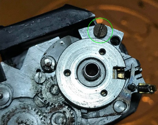
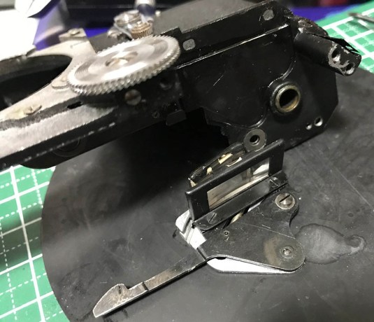
 You can now remove this cog. If I am not mistaken, this is coupled to the frame counter. I will have to warn you that this will sometimes drop to the floor if you’re not careful. See all that corrosion? We will have to clean those up using a toothbrush and some oil.
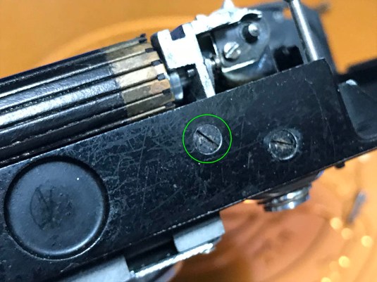
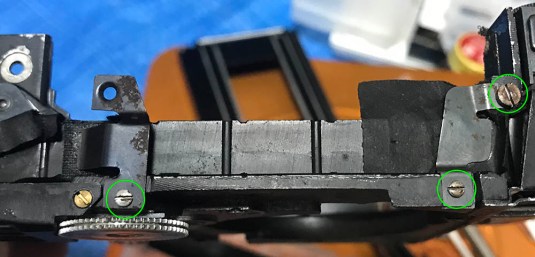
 To remove the shutter assembly, you must first remove a couple of screws. Here’s one of the screws that you should removed.
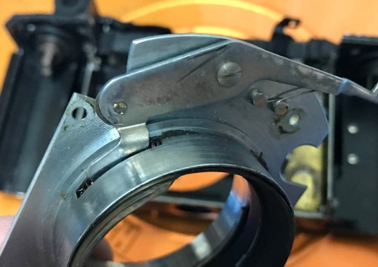
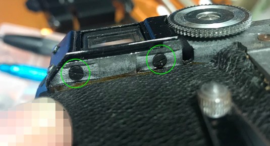
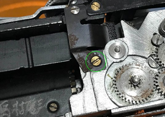 Here’s another on the other side. These 2 screws help secure not only the shutter but also the long glass mirror of the rangefinder so be careful with this. That glass part is delicate and it can be very brittle so go at it slowly. Note the original position of the screws.
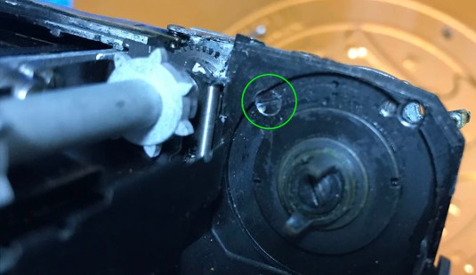
 Remove this big screw. found on the edge of the chassis casting.
 Here’s another one that you should remove. Be careful because there is a shim under it. I almost lost mine but fortunately I found it stuck somewhere.
 Here is another one. Don’t forget where each screw came from.
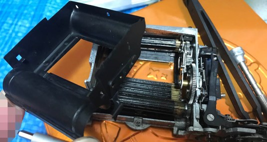
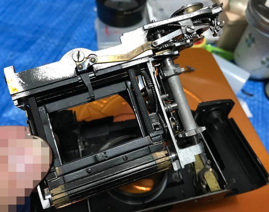 The whole shutter mechanism can now be carefully extracted.
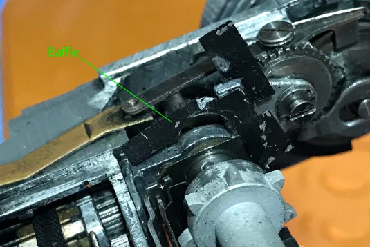 Be sure that you don’t lose this tiny baffle/light shield!
 The baffle can be pulled from the shutter crate. Be careful not to put this back the wrong way! It’s made of thin sheet metal so don’t warp it.
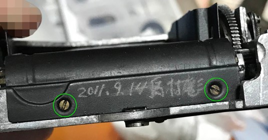 My shutter was put back incorrectly so I had to remove its protective cover so that I can reset the meshing of the curtains. Begin by removing these 2 screws.
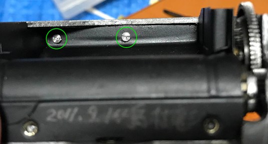 These are the last 2 screws holding down the protective cover You may be tempted to go and remove this but please don’t, you can only remove this through a series of steps. If it is stuck then don’t force it, just follow the next steps to find out why.
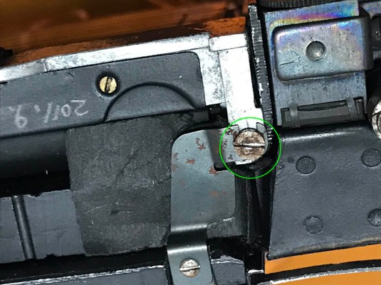
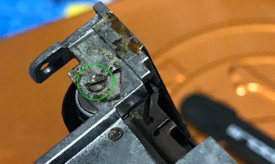 I was unable to remove the protective cover because my shutter was jammed so I had to remove the rear curtain roller first. To do this, you will have to remove the pin first. The pin’s head has a slot so you can turn the pin to disengage it. If it didn’t come out easily, it can be pushed from the other side using a small screwdriver.
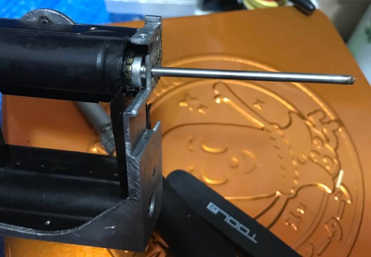 Here’s how the pin should come out. When putting this back, use a small strip of tape to secure it so it won’t fall out. Mine had a small strip of gaffer’s tape when I opened it first.
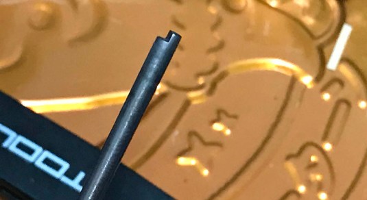 Here’s the other end of the pin. That notch is what’s holding it to the shutter crate.
 Once the pin is gone, you can then try and maneuver the 2nd curtain roller and roll it so the curtain now be relaxed. The other end of the roller has a cog and disengaging the cog from the main “fly wheel” will allow you to turn the roller freely. You will need to do this in case the curtain is jammed because part of the protective cover has a small tab at the side that also functions as a ramp and catch for the shutter curtain. That small part needs to pass-through a small notch on the roller so you can extract it safely. The roller needs to be turned in order for the small tab on the protective cover to slip through. I know this is complicated to explain without pictures but you will soon see what I mean.
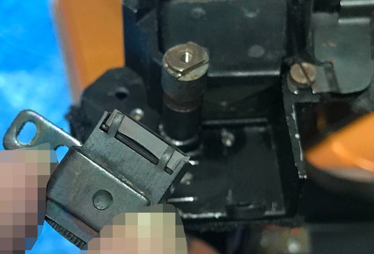
 You can now remove the cover. Take note that this is a functional part of the shutter so it should be handled with care. It’s not only there to act as a light baffle.
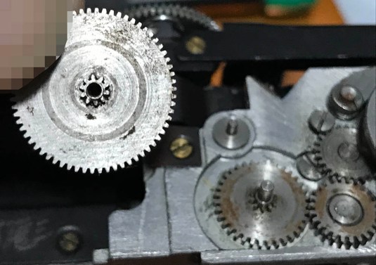
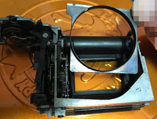
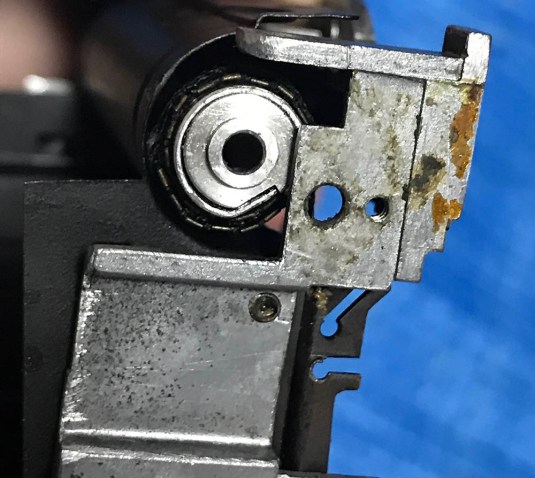
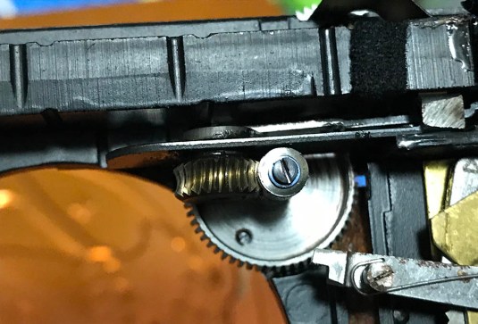
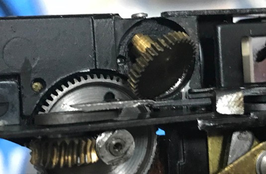
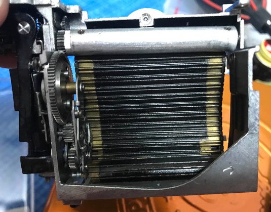 This is what we have at the moment. See the cog at the end of the 2nd curtain roller? The big gear (the “fly wheel”) is the main gear in the whole mechanism and it drives the rest of the gears here. If the shutter mechanism is jammed due to abuse or a botched repair job then this whole thing can be stuck and repairing the shutter is going to require you to strip the camera to this state. Notice the flat part beside the cog on the roller? That is the slot that I was talking about a few steps back wherein the tab on the protective cover has to clear in order for you to get it out safely.
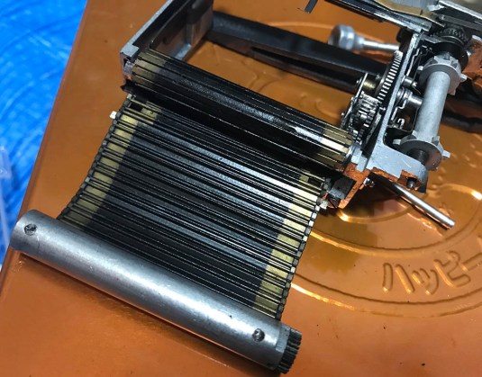
You can now carefully pull the roller out of the shutter crate. Be careful not to damage its ribbons/tapes while doing so. The ends of the curtain slats are also very delicate and they are very easily-bent so be careful when handling this.
Store the shutter mechanism in a safe place to prevent it from being damaged. Before we clean this thing and calibrate the shutter speeds, we will have to make sure that all of the springs and and escapements are working properly.
Resetting the Shutter:
Now that the upper roller is gone, you can now freely turn most of the gears and inspect if they are turning freely or not. Check for any loose springs or debris in the mechanism and see if that’s the cause of your shutter troubles. A spring that has undone itself means that an escapement isn’t working as it should which can lead to bad timings or a jam.
Resetting the shutter simply means that we configure the shutter gears so that they’re all back to their correct position after an exposure. While it seems pointless to do this since we are not going to reassemble the shutter yet but doing this will help us determine if it is possible to reset the shutter mechanism or not and see if we can fix any problems that comes out in the process. It’s better to find anything wrong now than later.
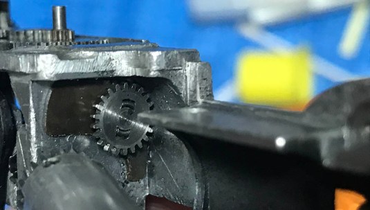
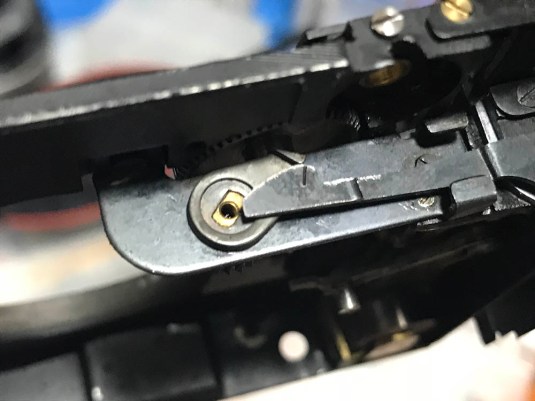
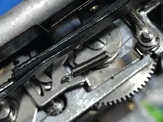 This is the reason why the shutter was jammed. The poor escapement was stuck so I had to manually free it up. See the teardrop-shaped cam? Rotate it so that the pointed part is pointing at the 6:00 position. Sorry for the out-of-focused picture.
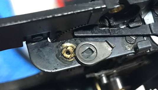
 Rotate the advance dial so that the pawl catches the notch on the brass collar then press the shutter button so it disengages again, simulating how it would be configured as if you just pressed on the shutter button after an exposure.
 Rotate this little cog all the way to the left (counter-clockwise).
That’s it for this portion. It’s short because there really isn’t much to discuss here. Doing it now and finding the problems early on will save you plenty of time later. We will clean this later in the next part after we remove the lower roller along with the curtains so it is safe to douse this thing with solvents and not worry about ruining anything that can be damaged in the process. Set everything aside and let’s work on the rest of the camera.
Disassembly (Helicoids):
The helicoid is used to focus your lenses by manually turning it or by using the focusing wheel above the rangefinder window. It’s coupled to the rangefinder assembly so it will affect the rangefinder if you turn it. Needless to say, this make it a complicated assembly. This can easily get dirty and will result in a gritty or rough focusing feel. Removing this is considered routine maintenance if you use your camera in the beach or any dusty place on a regular basis. While it’s not difficult to work with this, you will still need to follow a few things so you won’t get into trouble. Just follow my guide and you should be OK.
Before you begin working on this, focus it all-the-way to infinity and go out and focus on a far-away object to see if the rangefinder is aligned properly. Now, go back inside and do the task of taking notes. Take plenty of pictures of the rangefinder assembly’s mechanism from ALL angles, front and back. Study how the lever is configured while it is at infinity. This is very important because you will need to put things back the way they were later during reassembly. There really is no excuse for not taking notes.
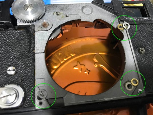
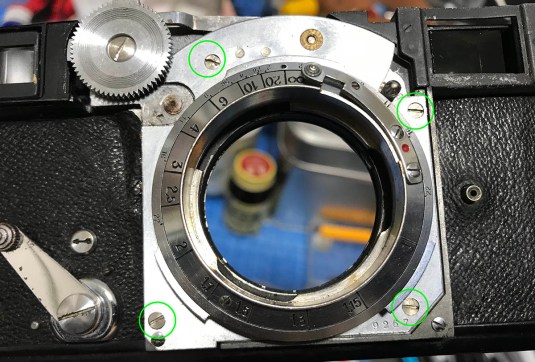 While the chassis is flat on the table, unscrew these 4 screws.
 Once the screws are gone, you can now carefully remove the helicoid. The reason why it is important that you do this flat on the table is because there are shims underneath the helicoid and you don’t want to drop these on the floor. The shims are there to adjust the helicoid and lens mount’s height so that your camera has the correct flange distance. The shims need to be on their correct place or else your focus will not be optimal.
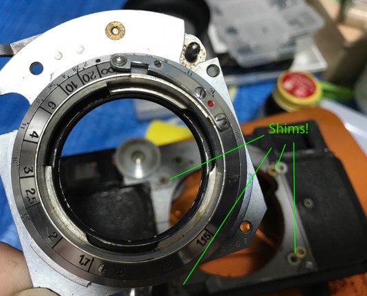
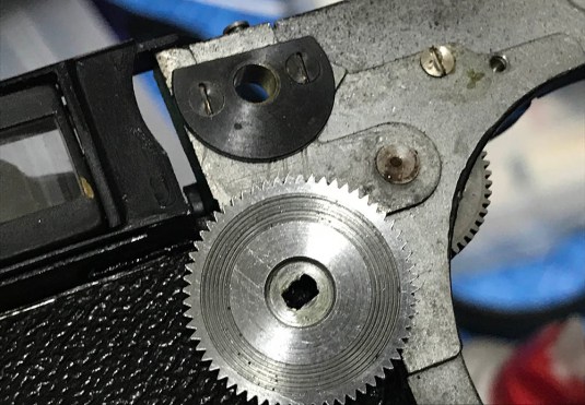
 Here are some of the shims. Never lose any of these! You may also want to check behind the lens mount and see if there are any shims stuck there. Remember, you don’t want to put them back the wrong way.
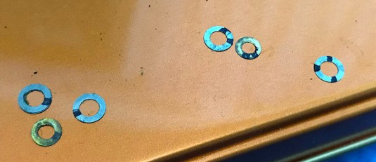 To help me determine which shim should go where, I used a marker and marked them so I will know which hole each shim came from.
 This is how the underside of the lens mount looks like. The end of the lever sinks into the sloth on the helicoid so that the helicoid stops turning and won’t allow you to get past the infinity position. When you press on the other end of the lever, the lock is disengaged so you can turn the helicoid freely. This is how the infinity lock works. Make sure the spring on the lever is not dislodged and never lose it.
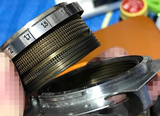
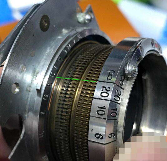 Press on the lever/lock so you can turn the helicoid. Turn it until it separates but do not forget to remember where it separated because this is also the same spot where it should mesh later during reassembly. Mine separated around this mark.
 Clean the male and female thread carefully with a stiff toothbrush. Clean it carefully so it is squeaky-clean. Once it’s clean, you can oil it a bit or just leave it dry-turning. It doesn’t really matter to be honest so long as it turns without any resistance or unevenness. If it’s rough to turn then your helicoid might be damaged or caked with corrosion. Clean these with an ultrasonic cleaner or use some lapping compound. I use jeweler’s rouge for this, I learned to do this at the family’s watch repair shop where I was an apprentice. If you’re new to this then practice on some junks first before you lap these.
That’s it for the helicoid. So long as you take plenty of notes then you should be OK. If you didn’t find any shims under the helicoids then you can only blame the previous guy who worked on it. Mine came with plenty of shims but I don’t know if they’re placed correctly or not because the only way to know is to measure the flange distance. Do not forget that the helicoids should mesh at exactly the same place they separated. If you forgot to take pictures or notes on where they separated then you’re going to have to waste time just to guess how these should mesh properly. If your helicoid is damaged due to impact, there’s little that you can do unless it’s minor. If you’re only dealing with minor impact damage or corrosion on the threads resulting in uneven and gritty focusing then you can just use jeweler’s rouge or any lapping compound to help correct that. I learned this trick while I was an apprentice at the family’s watch repair and jewelry shop. You apply the rouge to the the threads and manually work on it by turning them until you end up with a smooth helicoid. You do this while using successively finer rouge to polish the threads. This isn’t something a beginner should do and it’s a very delicate task best left to experienced and knowledgable people in this field. It will help, but it is not a guarantee that you will end up with a smooth helicoid. This will all depend on the extent of the damage.
Disassembly (Rangefinder):
The rangefinder of the Contax 2 is special. Its base is one of the longest ever mounted on a 35mm camera and it’s very accurate. The assembly itself isn’t difficult or complicated to understand, it’s just a long prism with a cylindrical prism on one end mounted on a lever and a diopter on the other end. The notes that you took in the previous step will come in handy later during reassembly. Be specially careful while working with this because it is made of several glass parts and you just cannot afford breaking any of them. Before you remove anything, take some pictures first so you will know how it was linked originally. This will save you plenty of time later because you have less margin for error. The glass parts are sometimes only secured with tape so be careful not to drop anything.
 This is what happens when you turn the focusing wheel, it turns the gear train and then this in turn rotates the helicoid through the teeth on its threads. It also turns a cam that’s coupled to the rangefinder’s cylindrical prism. I know this sounds complicated because it is over-engineered! Study how the end of the arm should be positioned on the cam when the rangefinder is set to infinity and take a photo of it. Turn the wheel and study how the mechanism works after you took your notes.
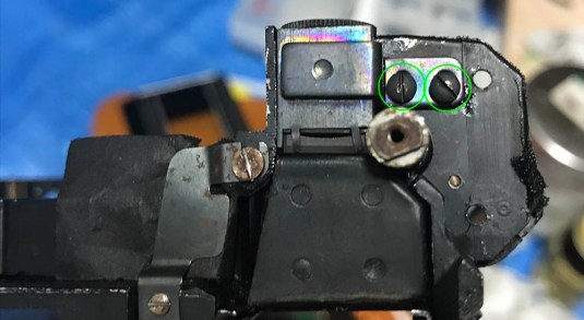
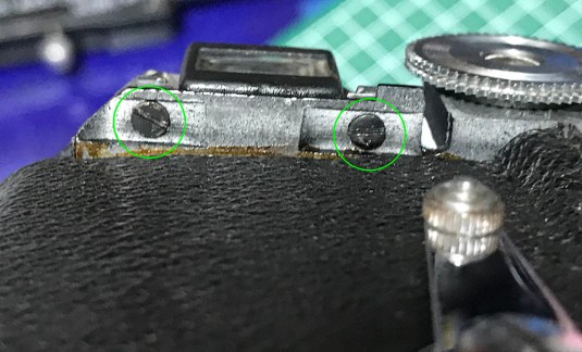
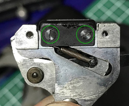
 These 2 screws secure the prism mechanism. Removing these will allow you to remove it from the chassis casting. You can also adjust the horizontal alignment of the rangefinder by loosening these 2 and nudging the whole prism assembly sideways, allowing you a bit of room to adjust your rangefinder.
 Removing the diopter is optional. I wanted to make sure that I clean the camera well so it had to be removed. This is a fine adjustment made at the factory so make some marks so you will know how this should be put back or you can adjust this later to your taste. My vision isn’t 20/20 so I chose the latter. The diopter is secured by the these 2 screws.
 This is how the diopter comes off. Notice that the holes for the screws are elongated? It’s like that so you can nudge the diopter housing back-and-forth.
 The diopter’s lens can be removed by prying on the prongs and picking the lens out. It is important that you clean this and the inner side of the housing properly. Clean the glass at the other end (eye piece) so the inner surface is clean. Mine was a bit dusty and after I cleaned the diopter, the difference was very obvious! No more milky finder! Don’t bother removing the eyepiece, it’s not essential to remove it and it’s fixed with a strong glue.
 Removing the long mirror/prism assembly is a simple but very delicate process. Unscrew these to remove the braces supporting this long piece of glass. Be careful not to crack it.
 Here it is. Clean every surface carefully with a lens tissue moistened with some spirits. It is important that you don’t scratch or crack this. If you dropped it then say goodbye to it and you can now call it Scheiße Ikon Contax. At least you now have spare parts.
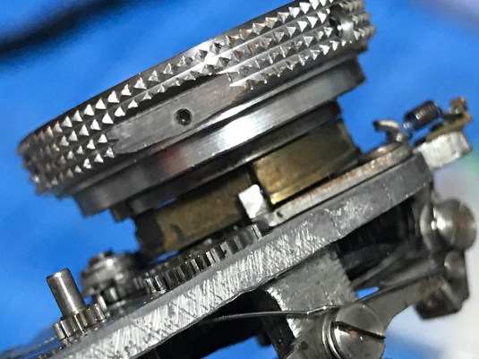
 The focusing wheel comes off just like this after removing the screw at the center. It does not really matter how this thing is oriented when you put it back since it’s free-turning. It does have to fit into the slot, that’s all.
 Here’s the other end of the focusing wheel. Dirt can easily hide underneath this so clean it very well. I would even polish the teeth with a toothbrush if I were you.
 This is the cam that turns as you rotate the focusing wheel or the helicoid. Notice that the swing arm/lever of the prism has jumped to the other side in this picture.
 Gunk can hide underneath cam and it’s essential that you clean this properly.
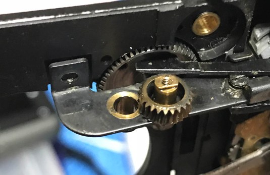 This is the gear that’s driving the cam. Again, take plenty of notes before you remove the parts here so you will know how they should be reassembled. Clean and polish the hole with a Q-tip and make sure that you didn’t leave anything there.
 The protective frame of the rangefinder can be removed after unscrewing 2 fasteners.
 Unscrewing this will allow you to remove the whole rangefinder prism assembly. It’s also the screws that will allow you to nudge the prism so you can adjust the horizontal plane of your rangefinder image by a small amount.
 Here it is. Handle this with care and never bend the arm.
 The front lens of the prism is secured in a frame. Unscrew these so you can remove the frame from the assembly so you can clean all of the glass surfaces properly.
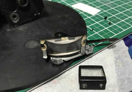 You can now clean everything properly! Notice that the cylindrical prism is cemented to its frame. Be careful not to disturb this or else you will have to realign this yourself. It is not an easy task and it’s something that you will prefer not to do.
That’s all for the rangefinder assembly. I clean every glass surface carefully with a tissue specially made for lenses and some Q-tips for places that I cannot reach. Be careful not to rub that long prism too much and remove the paint. If a stain won’t go away with alcohol try naphtha. Most of the time your breath will also work for stains that won’t respond to both alcohol and naphtha. Be careful not to scratch the glass while cleaning it.
Clean the parts of the rangefinder assembly properly and make sure that all of the grime is gone before you lubricate it. Pick on the teeth with a small wooden wedge or just use a Dremel with a pig bristle brush to clean it. Soaking it in cola works wonders but you will have to clean it really well afterwards. I seldom use cola because the cleaning can take a lot of time but it does remove some of the corrosion on metal parts. Don’t soak for a long time, 1-2 hours is probably long enough. Remember that cola is corrosive and it will eat the chrome or plating in the metal. Only do this for parts that aren’t part of a precision assembly or parts that were plated. Phosphoric/nitric acid is the active ingredient here. I rarely do this so I guess you shouldn’t do this, too!
Conclusion:
We’re now at the end of part 2. After disassembling everything, clean them very well and make sure that there are no traces of old lubrication in them. I usually dunk the all-metal parts and assemblies in a vat of naphtha or alcohol overnight then brush them very well afterwards. Any dirt that stayed will have to be picked by hand and a toothpick.
I will suggest that you don’t reassemble everything just yet because you will handle this camera quite a lot in part 3 when it’s time to adjust the shutter. All you can do now is to clean it very well and reassemble the smaller sub-assemblies. If you reinstalled these to the chassis casting at this point you will risk soiling or damaging them as you will handle the camera a lot in the coming steps. Just set them aside in a clean and secure place.
When lubricating the rangefinder assembly, make sure that you don’t use too much oil in the pivots of the prism because the oil will migrate to the glass over time. The gears need to be lubricated on their pivots, too. You can oil the teeth as well but don’t overdo it. Just a thin film of oil on the teeth is more than enough. Some people grease this but I won’t do it because old grease will cake into a dry gooey mess.
If you removed the housing of the diopter, you will have to re-adjust it after you reinstall everything on the rangefinder assembly. Moving the housing back-and-forth will allow it to be adjusted. Simply peek on the eyepiece and adjust it to your liking and then tighten the 2 screws to secure the housing when you’re satisfied.
Part 2 is quite long so I hope that you didn’t miss anything. Things will get more exciting in the next part and last part so please look forward to it. After the next part, we’ll begin with the Nikon S repair series. This will be the most in-depth article around in the net so I hope that you’re all excited!
Thank you very much for following this blog and supporting us through the donations. It will not come this far if not for your support. If you like the contents of this blog, please share this with your friends at social media or introduce this blog to your camera club. I hope that this blog will reach more people to entertain and educate. See you again in the next part. It was a very busy week but I found the time to finish this. Thanks again, Ric.
Help Support this Blog:
Maintaining this blog requires money to operate. If you think that this site has helped you or you want to show your support by helping with the upkeep of this site, you can simple make a small donation to my paypal.com account (richardHaw888@gmail.com). Money is not my prime motivation for this blog and I believe that I have enough to run this but you can help me make this site (and the companion facebook page) grow.
Leave me some tip?
Thank you very much for your continued support!
$2.00
Helping support this site will ensure that this will be kept going as long as I have the time and energy for this. I would appreciate it if you just leave out your name or details like your country and other information so that the donations will totally be anonymous it is at all possible. This is a labor of love and I intend to keep it that way for as long as I can. Ric.

Oct 24, 2024 @ 03:54:18
Richard, thanks so much for this detailed information. I am in the process of repairing a stuck shutter on an otherwise clean Contax II copy. I have freed the shutter, lubricated all of the shutter mechanism with Nyoil and watch oil droppers, and replaced the ribbon. However I cannot figure out how to reset the shutter and place the upper roller back in a synced position. I have fired the shutter and place the cam in the 6 o’clock position as you indicate. Now what do I do with the upper roller and curtain? Thank you in advance-