
Hello, everybody! Summers here in Japan can get really hot or rainy. All the heat and water will result in high humidity and we all know what that means. If you got the misfortune of having one or more of your lenses infected with fungi then head this fungus removal post to remedy the problem.
Introduction:
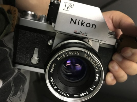
This is a part of our Nikon F series. Last time, we talked about how we can fix and clean the film counter display of Nikon F and now we are going to talk about how we are going to fix and clean the very popular Ftn finder!
 The Ftn finder can be distinguished from earlier models by the lever on it’s right side. This lever is used to open the 2 clasps that help secure it to the front plate of the camera’s face. There are 2 other earlier finders with a light meter attached and this Ftn finder is the last and most advanced iteration, making this the most popular metered head for the F so far.
We will not be discussing the operations of this thing as this is not the reason why you are here anyway and this is supposed to be a short write-up. Let’s begin!
Before We Begin:
If this is the first attempt at opening a lens then I suggest that you read my previous posts regarding screws & drivers, grease and other things. Also read regarding the tools that you will need in order to fix your Nikkors.
I highly suggest that you read these primers before you begin (for beginners):
- Essential tools
- Best practices 1
- Best practices 2
- Best practices 3
- Ai conversion
- Working with Helicoids
Reading these primers should lessen the chance of ruining your lens if you are a beginner. Also before opening up any lens, always look for other people who have done so in Youtube and the internet. Information is scarce, vague and scattered (that is why I started this) but you can still find some information if you search carefully.
I highly recommend that you also read my working with helicoids post because this is very important and getting it wrong can ruin your day. If I can force you to read this, I would. It is that important!
For more advanced topics, you can read my fungus removal post as a start. This post has a lot of useful information here and there and it will be beneficial for you to read this.
Disassembly:
This can be a pretty complicated project and I will advise that you send this to a repairman if you are not confident with your repair abilities or lack the correct tools. For people who are experienced with repairing stuff this will be a good project to keep your afternoon busy and productive.
You have to be careful where you start. I made some silly mistakes when I worked on this the first time around so I will show you the proper disassembly sequence here so you will not get confused.
Now, if you are not comfortable with your repair skills then you should let a professional do it for you. I am not a professional so my workmanship is a bit shoddy. The people on the list below can fix the foam problem for you.
- Jools Abel (UK) contaxrepairs.com
- David Hilos (Singapore) davidhilos@yahoo.com
You can contact them and ask for a quotation. I can vouch for the people above so do not worry about it. There are many techs out there with really bad workmanship and amateurs like me are even a notch better than some of them. Some of these techs work on the basis of commission so they rush things in order to finish more things in a short time. I’ve had people tell me horror stories. There is a saying in the car restoration hobby – “once you got a good mechanic, do not let go of him.“, the same can be said for camera repairs.
 Begin by saturating the edges of the rubber on the upper part of the finder with alcohol to soften the contact cement (rubber cement) that was used to make it stick to the surface of the top cover. Reapply until the leatherette can be peeled off effortlessly.
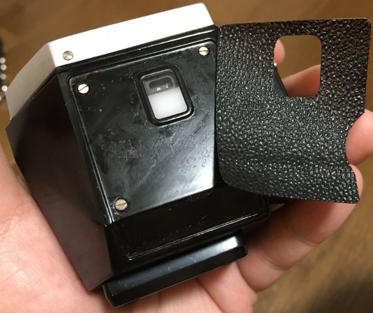 The leatherette came off after about 30 minutes of alcohol treatment. Be careful not to rip this leatherette. Replacement leatherette sheets are available but you really do not want to bother with it’s replacement. I will make a template for this and upload it to the net one of these days just in case you ruined yours.
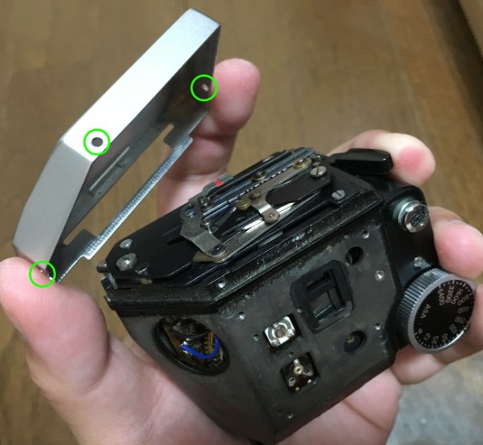
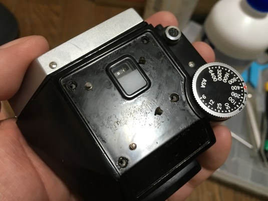 Now that the leatherette is gone, you can now access these 4 screws on the top cover. Just unscrew them to get the top cover off.
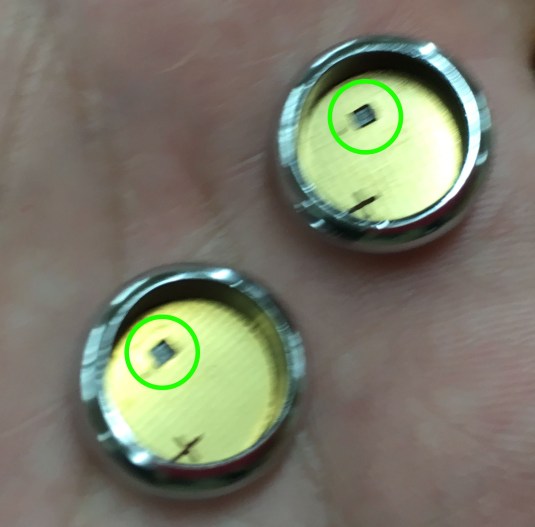
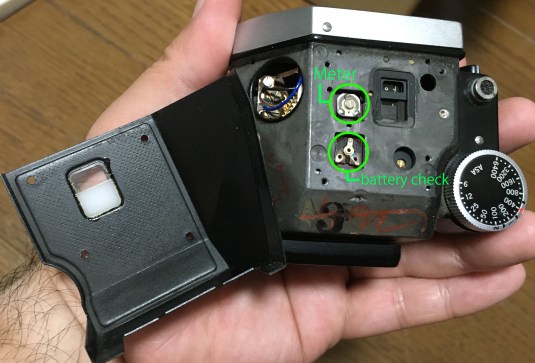 With the top cover out of the way, you can now access these 2 potentiometers or whatever people call these. One is for meter adjustments and another is for battery check. I did not have the need to fiddle with the battery check but I had to adjust my meter so that it is in line with my light meter and DSLR’s.
Be careful with the meter readout window’s plastic cover, you do not want to accidentally poke it and pop it out of place.
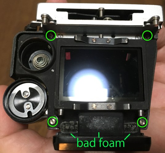 Remove these four screws to open up the finder housing. From this view, you can see the places where the old foam was positioned. They were all dry and crumbled when I used my blower to blow off whatever remained. We will replace these with fresh ones later.
IMPORTANT: Even with the 4 screws gone, you will NEVER be able to separate the housing until a few steps later so do not attempt to open it now.
At this point, you should also remove the batteries before proceeding because you will be dealing with the electronics soon.
 Now that the batteries were mentioned, I would like to show you these adapters that I got. They will take in normal LR-44’s (1.5v) and convert them to 1.35v. That is the same voltage of the original type of batteries these finders take (mercury). Unfortunately, the mercury cells are not openly available anymore due to their toxic chemistry. The voltage difference is enough to affect the light meter’s readout and these adapters help prevent that to some extent.
The adapters are also needed in order for the LR-44’s to fit into the compartment because the old mercury cells’ casing is shaped differently. There are other alternatives including the popular Wein cells and the 625A cells but this adapter is pretty good but the initial cost is something that turn many people off. In the long run these adapters will pay for itself so I recommend that you get these (LR-44’s are cheap).
 Before you can separate the housing you should remove the front plate first. Remove the 3 screws and carefully remove the front plate. Make sure that you do not damage anything in the front like the delicate connections to the rabbit ears and the mechanism underneath the front plate. The circles on the picture show where these screws were previously.
If you see some grey or black paste in the aperture feeler mechanism, simply use a cotton swab saturated with lighter fluid and wipe away the gunk. The gunk is a mixture of metal filings and old grease. It may not hamper with the operation of the mechanism but it may affect how smooth you turn your aperture ring when the lens is connected to the finder by way of the rabbit ears. You do not need to lubricate this part, just keep it clean.
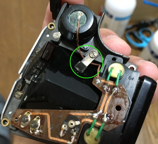
 A few steps back, we removed the 4 screws holding the housing together but you will never be able to get the housing apart until this step. Simply loosen these 3 screws a little bit but never remove them from their holes. Simply slide the ground and terminals (is that what these are called?) away from their respective screws and you’re done. These 3 connections belong to the top part of the housing so you will not be able to open this thing up until you disconnect these things.
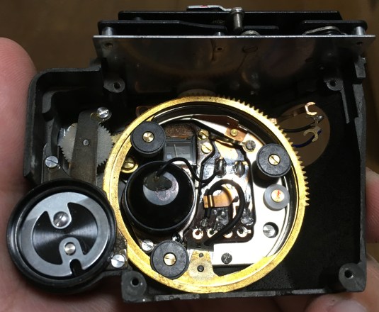 You can now safely separate the housing. As with the aperture feeler mechanism, you will want to look for solidified grease/filings in the big brass ring and wipe them clean while this part is accessible. Remember not to oversaturate the cotton swab with alcohol or else you will soak everything up with alcohol!
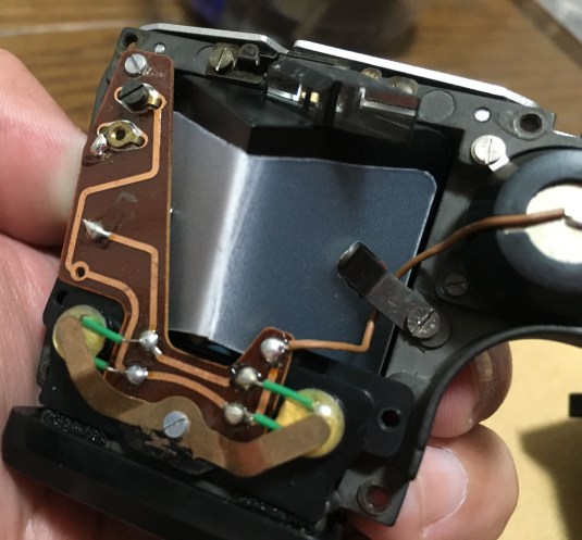
 Here is the bottom half of the housing. The printed circuit board (PCB) is brittle so be very gentle when handling this. I accidentally cracked one of these and I was not even forcing it and that ruined my evening so I had to ask my wife to bring me a glass of ice-cold Coke to bring the situation back under control or else I will turn into a big green monster.
Looking at my notes for that ruined PCB, there is a hairline crack present. That and the age of this part made it a delicate part. I learned my lesson so I hope that you do not make the same mistake. I can fix the ruined PCB with a little epoxy, copper wire and solder but that will have to wait until I get into the mood to tackle that because the crack occurred in an inconvenient place with 3-4 connections but thankfully the important parts were spared.
Check the picture and you will see 4 brass washers in each corner of the lower housing. Do not lose any of these and secure these with a dab of nail polish on the other edge / rim of the washer.
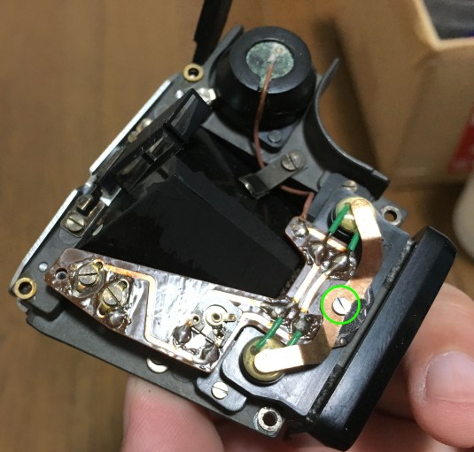
Unscrew the encircled part and proceed to the next step…
 Now it’s time to remove the cadmium light sensors. Remove this brass brace thing. This is responsible for securing the cadmium cells in place by applying pressure into it. These are old and many do not function properly anymore. Symptoms will vary from a jumpy needle to faulty readings. Replacement parts can be salvaged from other finders or bought from Akihabara. The Japanese camera repair magazine Camera GET (カメラGET) sometimes show listings of who sells these items and where. Yes, camera repair and maintenance is a real hobby here in Japan.
 Before you proceed with removing the light metre electronics you should unscrew this part first because a wire runs under this brace.
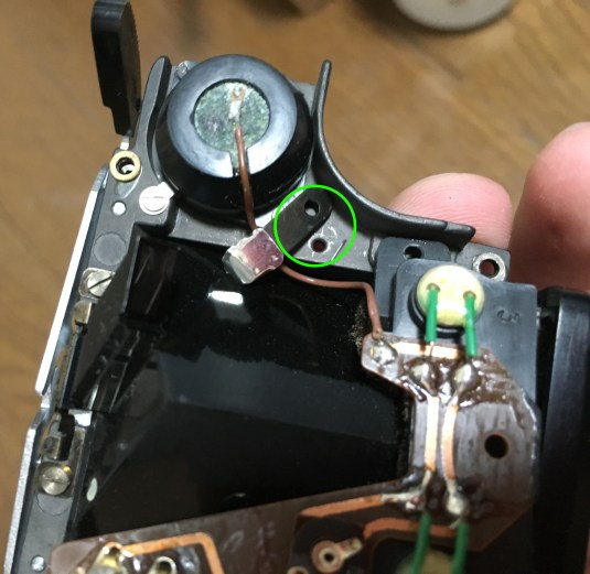 Now that the brace is gone, you can now safely remove the electronics (next step)…
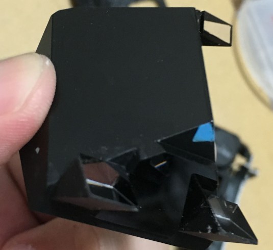
 Just look at that thing. In the first decades of Japanese SLR manufacturing, people did not realise that the foam seals will rot on day and harm the prism. I remove whatever is there mechanically by using a toothpick and then scrub it with cotton swabs and alcohol. I will require several tries and plenty of Q-tips so be patient. Be careful not to further damage the prism by being gentle with the scrubbing.
A damaged prism will result in irregular shapes when you peep into the viewfinder and it is very annoying to see this every time you peek into finder. There are a few ways to fix the corrosion and I will discuss it in a later blog post as soon as I find a good and reliable way of fixing this. For now, I will just get by with replacing this damaged prism with a good one.
By the way, these corroded foam seals that directly get in contact with the prism will not be replaced. Instead, we will be using black electrician’s tape in place of the foam. Stick a strip of tape in the cadmium housing with the sticky side facing away from the prism. Just be sure that you do not obstruct the lenses of the cadmium cells and cut some parts away if you have to.
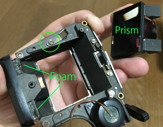 To completely clean the prism housing, simple loosen the circled part to remove the prism and remove the remaining foam seals. The brass part in between the foam is the “tunnel” or baffles for the viewfinder. That thing is loose and not glued in place so be careful.
All of the foam seals used throughout most of the finder are of the 1.5mm (thickness) type I think. I have the 1.5mm and 3mm varieties and these looks like they are made form the 1.5mm type. Please do your own research.
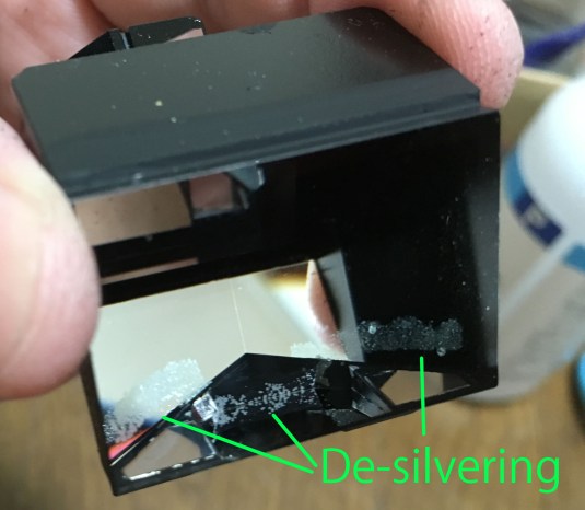 Now, a close-up view of the nasty corrosion on the prism. This is caused by the foam seals found on the plastic cadmium housing. I am really itching to get this thing fixed!
 This is a good replacement prism that I got from another finder and all finders with good prisms aren’t cheap! It hurts me inside just thinking about this so I will skip the topic for now.
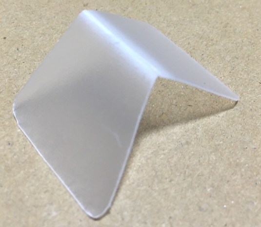 I made a cover to protect the replacement prism from the plastic cover of a notebook. The part that this thing covers in the prism do not get into contact with any foam seals so you can even argue that this is useless but I want to be safe. This thing is a popular mod in the Olympus community here in Japan to protect the prisms of the OM series of small cameras. Nikon F2 finders (apart from the DE-1) have this plastic cowl so I guess Nikon learned from their mistake.
 OK, the only part that gets in contact with the foam is the small ridge on top of the exit to the viewfinder but whatever…
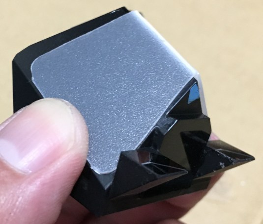
 Here is the cover with everything else in place. This is the PCB that I ruined, I can see the hairline crack from this angle. Notice that the electronics are clean.
 And now we are back with the old and dirty PCB. Shit happens…
Conclusion:
Before you put the top cover back, be sure to adjust your meter while it is accessible. Use a precision minus (-) screwdriver and adjust the small screw on the potentiometer until the exposure is where you want it to be. Please refer to the pictures in the earlier steps to find where the potentiometer is.
That’s it for today! Our short write-up ended up being a long a long teardown guide. If you have any ideas or suggestions, you can reach me via our community Facebook page or the comments sections so I can add your feedback to this page. Until next time, Ric.
PS: Special thanks to Keith and Peter for pointing out that the photosites were not made of selenium but cadmium (CDS).
Help Support this Blog:
Maintaining this blog requires money to operate. If you think that this site has helped you or you want to show your support by helping with the upkeep of this site, you can simple make a small donation to my paypal.com account (richardHaw888@gmail.com). Money is not my prime motivation for this blog and I believe that I have enough to run this but you can help me make this site (and the companion facebook page) grow.
Helping support this site will ensure that this will be kept going as long as I have the time and energy for this. I would appreciate it if you just leave out your name or details like your country and other information so that the donations will totally be anonymous it is at all possible. This is a labor of love and I intend to keep it that way for as long as I can. Ric.

Jul 17, 2016 @ 15:04:52
Hi Sir! Appreciate all the informative content you have been posting 🙂 been following your blog since early this year and by far have been very impressed with your articles 🙂
Aside from the leatherette template of the FTN finder you mentioned you would be posting, hope you can also post the leatherette templates pf the Nikon FM/FE/FM3a series as I am really itching to have mine redone well but sadly, the PH has really no dependable shop to have it done with a nice output.
Looking forward to it Sir Richard! Cheers and more power!
Jul 17, 2016 @ 15:06:57
Hi Sir! Appreciate all the informative content you have been posting 🙂 been following your blog since early this year and by far have been very impressed with your articles 🙂
Aside from the leatherette template of the FTN finder you mentioned you would be posting, hope you can also post the leatherette templates pf the Nikon FM/FE/FM3a series as I am really itching to have mine redone well but sadly, the PH has really no dependable shop to have it done with a nice output.
Looking forward to it Sir Richard! Cheers and more power!
Jul 17, 2016 @ 15:14:20
Check your pm sir, ill show you an easy way to make one
Jul 17, 2016 @ 15:43:38
Hi Rchard. Just a small note: The photocells in the FTn finder are CdS(Cadmium DiSulfide) cells, not selenium cells. -KB
Jul 17, 2016 @ 15:45:55
Thanks, Keith! Somebody actually told me that as well. I will correct it tomorrow as my baby is literally sleepingnon top of me. Ric.
Aug 22, 2016 @ 20:00:19
Hello, Richard. This will be a very helpful guide for me as I recently acquired two Nikon F Photomic FTns – one in chrome and one in black. I was fortunate in that the foam has not eaten though to the silvering on the prism in the chrome version, but I definitely need to get in there to remove the foam and residue before the damage occurs. You mentioned that there are ways to fix the corrosion, and that you will feature info on that in a future blog. I will look forward to that post as the black finder did not escape the damage. I am very much enjoying your blog. Keep it coming!
Aug 23, 2016 @ 01:03:23
Thank you, mr. Bee keeper!
I am Itching to try a resilvering method but i need to test it myself first. If I successfully resilvered my prism, i will show it here in the blog. Thanks again!
Feb 21, 2017 @ 10:13:35
Very interesting. Most of the DEAD Nikon F heads are due to DEAD CdS cells. A) Did you replace them while you were at it? B) Sover say that the CdS Cells used in the Nikon F are different than the ones used in the F2. Do you have a Source for these CdS cells??
I recently changed my Photomic T head for a FTn head. Why? Because I had a nasty BLACK line that bisected the finder I was told it was caused by the degrading of the foam. My big fear is that the CdS cells will give out.
One thing I would like to do is change my Mercury Batteries for some Silver Oxide Batteries.
Have you thought about re-silvering the prism? If they can re-silver mirrors they should be able to re-silver a prism.
Thanks for the info. I’m bookmarking this page.
Feb 22, 2017 @ 04:49:00
Hello, Bob!
Glad that you bookmarked this page! There are shops selling the CDS cells here in Japan but without the housing, however there are individuals selling them from time-to-time on camera repair magazines here. What I do is salvage some from junks, especially Nikkormats since they are dirt-cheap.
As for re-silvering, there are people that can do that like people who restore headlights. You can approach them. The correct way is to use vacuum deposition with aluminium. Aluminium is brighter than silver (compare F and F2) and telescope shops that cater to hobbyists will have contacts for people making their home telescopes. If you find one who will accept small orders, please tell me. Ric.
Mar 20, 2017 @ 15:09:46
Hello Mr Shaw, would you by any chance have time to fix or quote me for a repair on my FTN meter? Is it even worth paying to get one repaired or is it better to buy a working one?
Mar 21, 2017 @ 02:58:18
Hello, Marlon!
It’s Haw 😀
I am currently busy so I cannot accept any jobs plus I am not a professional so my quality would suck. However, I know a few people will do that for you. It is not difficult so lung as you have the right tools.
I am not sure if I have made an article about fixing the FTn meter. I replaced mine some time ago from a junk that I got and it’s all good. It is not a difficult task but you will need to solder things here and there. Be sure to also use the correct batteries. If I haven’t made an article yet, I will write one when I am not busy. Ric.
Mar 22, 2017 @ 17:39:07
Thank you Richard. You did post that video where you did fix the meter. I’d have to watch it a couple of times to see if I’m able to do those things at home.
Thank you!
M
Mar 23, 2017 @ 06:26:26
Hello, Marlon.
I think there is one on the net that teaches how to work on the Ftn but I am not sure if he went as far as changing the meters. I think you should look for a donor body first. In my case it is easy to find cheap junks here in Japan but it may be different in your case. I salvage my last meter from a junk Ftn. Ric.
Mar 23, 2017 @ 15:49:55
You’re right, finding a junk replacement to work on or replace might be best. Thank you!!
Mar 23, 2017 @ 08:22:09
A few other comments:
1) I want to use Silver Oxide Batteries for my F. You mentioned that there are adaptors that will convert the 1.5 or 1.55V to the 1.35V used by the Nikon F . Do you have a name, model number, and source where you can buy these battery adaptors?
2) I recently had Sover Wong service my DP-2 head (on my F2S) and while it did not really need it I had him change out the Prism for a new one. He sent me back the old one, which is still in pretty good shape. Do you know if the Nikon F Prism is interchangeable with the F2 Prism?? I know that the F and F2 Screens are interchangeable I’m wondering if this might also apply to the prisms.
3) You state, “I did not have the need to fiddle with the battery check but I had to adjust my meter so that it is in line with my light meter and DSLR’s. …Before you put the top cover back, be sure to adjust your meter while it is accessible. Use a precision minus (-) screwdriver and adjust the small screw on the potentiometer until the exposure is where you want it to be.”
OK Given that I don’t have access to to a DSLR, and you don’t mention HOW to adjust the light meter, could you tell us how to adjust the light meter so it is reasonably accurate.
4) For my own knowledge. On my F T Photomic Head, and on my F2 Photomic (DP-1) head, and on my F2S (DP-2) head, the meter prong that engages the “Rabbit Ears” points FORWARD which makes it easy to remove the lens as it simply lifts straight off of the prong, but I noticed on my F FTn head the prong points BACKWARDS towards the camera body. Is this something strange with my FTn head (like someone botched a re-assembly and installed it backwards) or are all FTn heads like this?? After studying my FTn head and a few pictures of the bottom of various FTn heads it *seems* that this backwards orientation of the “feeler” prong is normal. But I want to confirm that it is not just my head that has the backward prong. It makes it a pain for removing lenses that much I know for sure.
5) You mention you do not use foam but black tape: “By the way, these corroded foam seals that directly get in contact with the prism will not be replaced. Instead, we will be using black electrician’s tape in place of the foam. Stick a strip of tape in the cadmium housing with the sticky side facing away from the prism. Just be sure that you do not obstruct the lenses of the cadmium cells and cut some parts away if you have to.”
What “cadmium housing” are you talking about?? If the sticky side of the tape is pointing AWAY from the prism, is it pointed INTO or taped to the INSIDE of the “cadmium housing?
6) After saying that you will not be using foam and will be replacing it with the black tape, you then say, ” All of the foam seals used throughout most of the finder are of the 1.5mm (thickness) type I think. I have the 1.5mm and 3mm varieties and these looks like they are made form the 1.5mm type.” This is confusing. Could you please clarify since I thought we were getting away from using foam.
Great post, I hope to continue learn from this. I will be very curious to find out about those battery converters and where I can buy them from.
Mar 23, 2017 @ 09:42:06
Hello, Kat!
Holy shit that was a mouth-full! Thank you for enjoying the site, it’s people like you that I want to reach out to and people like you motivate me to maintain this blog.
1) Go to Google or ebay and search “MR-9 battery adapter”. I am not endorsing anybody so caveat emptor.
2) Depends on which heads. For the metered heads, they are NOT interchangeable.
3) Get a camera that is known to give accurate meter readings. Set your Ftn and play around with the potentiometer so that they both give roughly the same reading on different environments. Indoors, outdoors, artificial lighting, sun, sky, what have you.
4) I am not so sure about this. The best way is to search Google and look at the pictures of the feelers and see which way they point. I will admit that I never paid any attention to these.
5) The cadmium cell housing is the plastic thing that holds the photodiodes.
6) I replaced all of the foam seals EXCEPT the ones that come into contact with the prism, this is what I have been doing since. The seals are there for something but this will work without it. To avoid the prism getting damaged, I made a plastic cover for it.
In case you are unsure of anything, you can ask Mr. Sover do the repairs. He may be busy but he is still one of the best options for many people. This blog is just to inform people and to help repairmen who wants to see what they are going to get into in advance.
Ric.
Jun 15, 2018 @ 20:40:26
Hello, Richard,
Much admiration and many thanks for what you are doing with your website, and I sent you a few dollars for a beer shortly after discovering it. However, I’ll buy you another for this column on the F Photomic meter. I’ve “overhauled” my photomic finder and soldered in a 1N4006 diode ahead of the battery chamber so that I can use 1.55V silver oxide 357/303 cells in adapters I bought on the ‘bay. The camera is in excellent, under-used condition; my meter’s resistor ring was quite clean (though I did clean it with an alcohol swab). Looks to me like nobody else had been in there before me since it was made in 1971. The prism foam was going bad so I cleaned it off and replaced it with 1mm self-adhesive polyester felt rather than tape. This seems to have worked well, there is a visible hint of the former nastiness can be seen in the finder, but it is not bad at all, really. Not bad enough to justify re-silvering if I knew how or where to do that. Cleaning the internal dust from the prism surfaces quite brightened things up, too. The thing that perplexes me is that my meter adjustment is now at its clockwise limit. Adjusting the battery check helped bring the meter needle further into line, but the meter adjustment will still not let me adjust the needle to dead center. I think the camera will tend to overexpose by as much as a third of a stop if my settings center the meter needle – not a big deal for film, but I wonder if my diode modification is responsible for the condition, or are my CdS cells perhaps tired from so many years on the bench? Have you any advice for me?
Jun 21, 2018 @ 16:01:35
Hello, If you are refering to the FTN finder, there are 3 resistors that you can adjust there. be careful with the diodes specially with the direction. a note on diodes, if its overexposing too much then its lifespan is almost spent. I will look for suitable replacements but for now I am only able to salvage junk parts. Ric.
Jun 21, 2018 @ 17:01:48
Hello, Richard,
I hadn’t realized that there are three variable pots in the finder. Of course, there are the two on the finder housing, under the top cover. The third I presume must be on the printed circuit board (pcb) inside the finder. Your photos appear to show two pcb’s: one with a variable pot, and one without. The pcb you say that you “ruined” does not have a variable pot on the pcb; the pcb in your next photo has a variable pot – a 3rd pot – on it. Now that my finder is closed up again, I can’t recall if mine has that variable pot on the pcb. I should have photographed it! I’m looking for a junk meter to delve into this again. My finder is working satisfactorily; I shot a roll of film with it and all seems fine, so I don’t want to open it again until I’m sure it needs more “help”.
Can you offer any guidance on adjusting the (third) pcb pot?
I’m certain that I installed the diode properly; the meter would not work at all if the diode polarity was wrong because it would block power to the meter instead of passing current with a small voltage drop. It’s the voltage drop provided by the diode in its proper polarity that permits use of 1.55V silver oxide batteries.
Looking at the CdS photo resistors, it seems that it ought to be a fairly straight-forward task to replace them with new CdS resistors from Adafruit or Mouser or other electronics parts dealers. The challenge would be to fit the new resistors to the plastic housing in the meter so that all is dimensionally correct and clipped in place by the brass clamp. It appears that new Cds resistors are physically smaller than those used by Nikon in the day; however, the plastic housing design inside the finder could easily accommodate smaller sensors mounted in something non-conductive. I see that Sover Wong has had some made up in casings that are the same dimensions as the old Nikon CdS resistors, and he can drop them in place of the old CdS cells in F2 finders.
Aug 23, 2018 @ 07:39:00
HIHI
What is the spec of the Cds?
Sep 03, 2018 @ 00:14:57
Hello.
Sorry but I have no data. Ric.
Oct 14, 2018 @ 18:54:34
Hello, Richard!
Cool article, absolutely!
May I ask you a question?
I recently got a F with a photomic FTn, where those 2 screws beside the bad foam from pic #6 here are missing. Do you have an idea where I could get those 2 screws??
Haven’t found anything yet… 😦
Much appreciate any hint!
Thanks a lot in adavance and keep going with this website!!
Best wishes,
Thomas.
Nov 03, 2018 @ 00:05:18
Hello, Thomas.
Try your model railroad shop, if not just salvage some from a junk camera. Ric.
Oct 16, 2018 @ 08:37:53
Hellohello,
Can you let me know please where I can get those screws from pic #6 and these adapters for the 2 batteries?
Thx a million!
BR,
Thomas.
Nov 03, 2018 @ 00:04:17
Hello. You can get some from spares. I usually buy junk cameras to salvage for parts. Ric.
Dec 03, 2018 @ 20:43:28
I have found that there are optical differences in the production series of prisms for the Nikon F Photomic TN finder. I substituted a clean prism from finder serial #647507 (date code: 7002) into an older finder serial #556970 (date code: 6910) and discovered that the meter needle display projects too high in the viewfinder. I’ll have to find a clean prism from a finder whose serial number is closer to that of finder serial #556970.
Mar 12, 2024 @ 01:01:58
Wow thanks for the very detailed information but I think ide rather pull my own Teath out it’s the repair man for me ..