
Hello, everybody! We’re going to continue with part 3 of our Nikon S2 series and we’re going to tackle the more complex mechanisms in this article. I’m going to make-up names and terms for the parts here so don’t treat this as a definitive guide. This is designed more as a walk-through to educate you on how the Nikon S2 works. If you missed part 1 and part 2 then read them and come back after so you won’t get lost. This series is proving to be one of my more popular camera repair series so I hope that you’ll enjoy this.
Continued:
The Nikon S2 is Nikon’s 2nd consumer camera design. The Nikon I/M/S series is merely an evolution of the Leica Barnack cameras and is the best attempt by any Japanese company in making one. The Nikon S2 is more advanced, it laid the foundations for Nikon’s best rangefinder camera, the Nikon SP. This is such a big departure from the Nikon I/M/S and it has features that you can even find on the Nikon F. This is a very important camera for the Japanese, I see it as an attempt by the Japanese camera industry to distance itself from its reputation of being a copy-cat and Nikon did it after just one model. This was the best that Japan had to offer back then.

What a handsome camera! I love the Nikon S2 so much that I own 2. These 2 cameras were bought as junks, sold for parts and were restored by me. This is how my collection grew and repairing my own gear saves me money and I am also assured that my cameras will work properly. I use my cameras all the time and they don’t sit inside the cabinet collecting dust.
If you wish to understand the Nikon F then you’ll want to understand how a Nikon S2 works. It’s interesting to see how this design evolved into a camera that many people consider to be the perfect SLR from Nikon’s golden age. It is important to note that this was written for your entertainment only so do not treat this as a repair manual. This was written for the Nikon historian, a look into the internals of the Nikon S2 and how it shaped future designs. It’s not wise for the beginner to use this as a repair manual, if your camera had to be repaired, send it to a repairer but make sure he’s legit. There are many bogus repairers out there and the only way to find out who’s the real-deal is to ask around online. Good repairmen aren’t cheap for a reason because the skills and experience required for a successful repair requires many years to learn and the tools involved aren’t cheap. You are also paying him for his health since repairing cameras involves hazardous chemicals and time. It’s now time to begin part 3, enjoy!
Before We Begin:
If this is your first attempt at repairing a lens then I suggest that you check my previous posts regarding screws & drivers, grease and other things. Also read what I wrote about the tools that you’ll need to fix your Nikkors.
I suggest that you read these primers before you begin (for beginners):
Reading these primers should lessen the chance of ruining your lens if you are a novice. Before opening up any lens, always look for other people who have done so in Youtube or the internet. Information is scarce, vague and scattered (that is why I started this) but you can still find some information if you search carefully.
I highly recommend that you read my working with helicoids post because this is very important and getting it wrong can ruin your day. If I can force you to read this, I would. It is that important!
For more advanced topics, you can read my fungus removal post as a start. This post has a lot of useful information and it will be beneficial for you to read this.
Disassembly (Film Advance/Selector Parts):
This part will cover more than just the section’s title suggests. I will include parts that have no relation to film advancing or speed selection here. I only named it that way for convenience. This part is very critical so taking plenty of notes will help you later. Take as many photos as you can specially of the shutter in both cocked and relaxed states for reference. You do not want to remove something without any idea about how to put it back again. Most of the parts here rely on proper positioning and you may find yourself going in and out the camera just to position things properly during re-assembly. It is wise to always check if all the parts are aligned properly before fastening the last screws. This part is intimidating for beginners and rightfully so, this is best left for the specialists who know what they’re doing! Not having the right tools or skills is a sure way of butchering a camera that could’ve been saved by somebody competent.
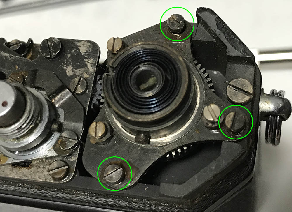
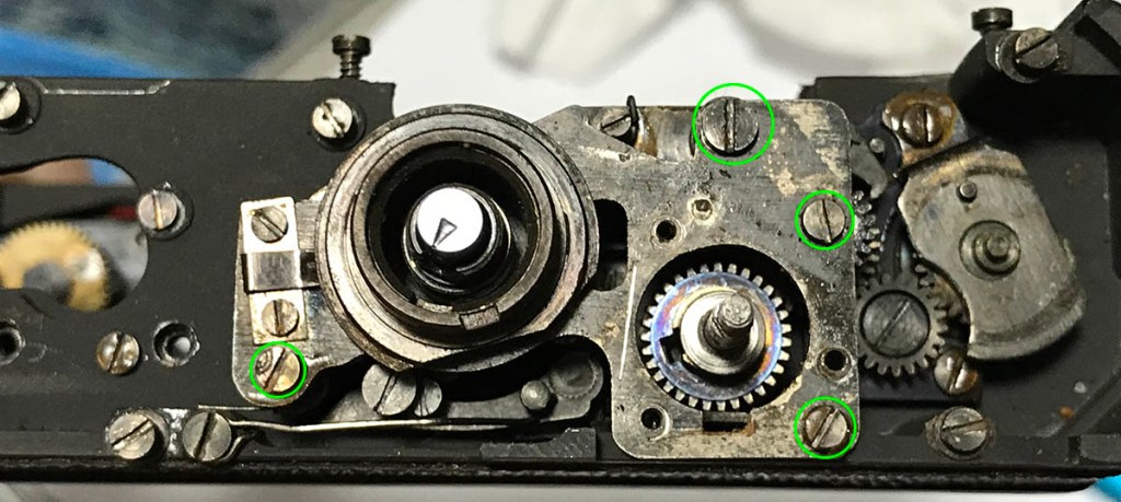
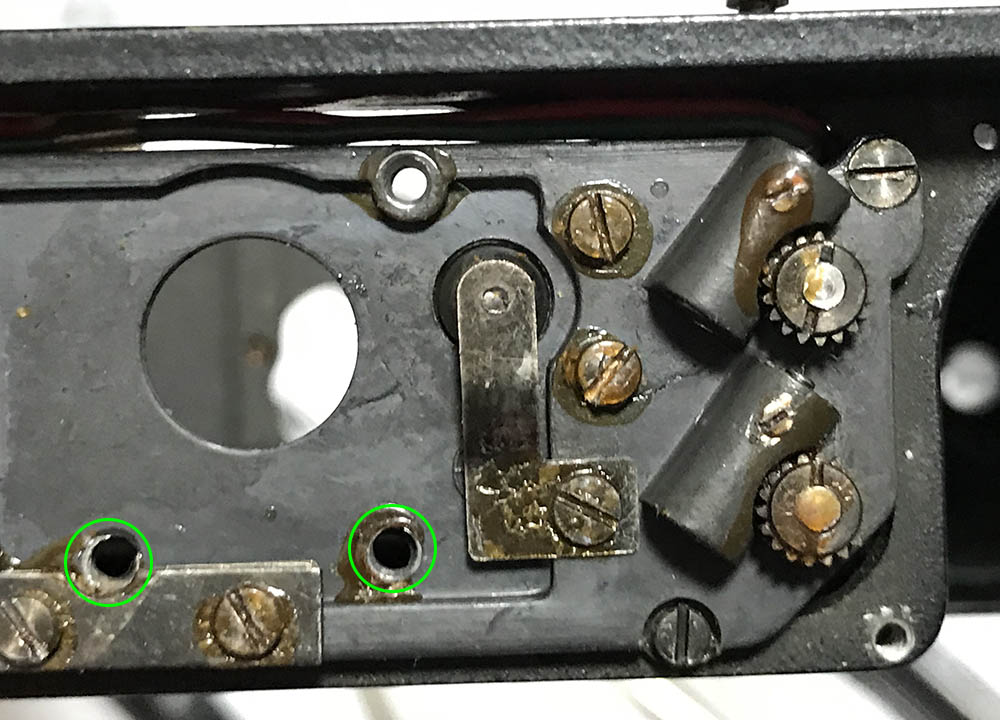
Remove these screws to remove the film counter and ratchet mechanism. It can be difficult to remove these as they were sealed at the factory, you can use solvents to soften the seal before you remove these, heating them with a soldering bolt will also help a lot. These can sometimes snap so you must be careful and use the best-fitting driver that you have. Note that one of them is smaller, remember its position.
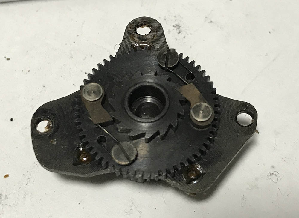
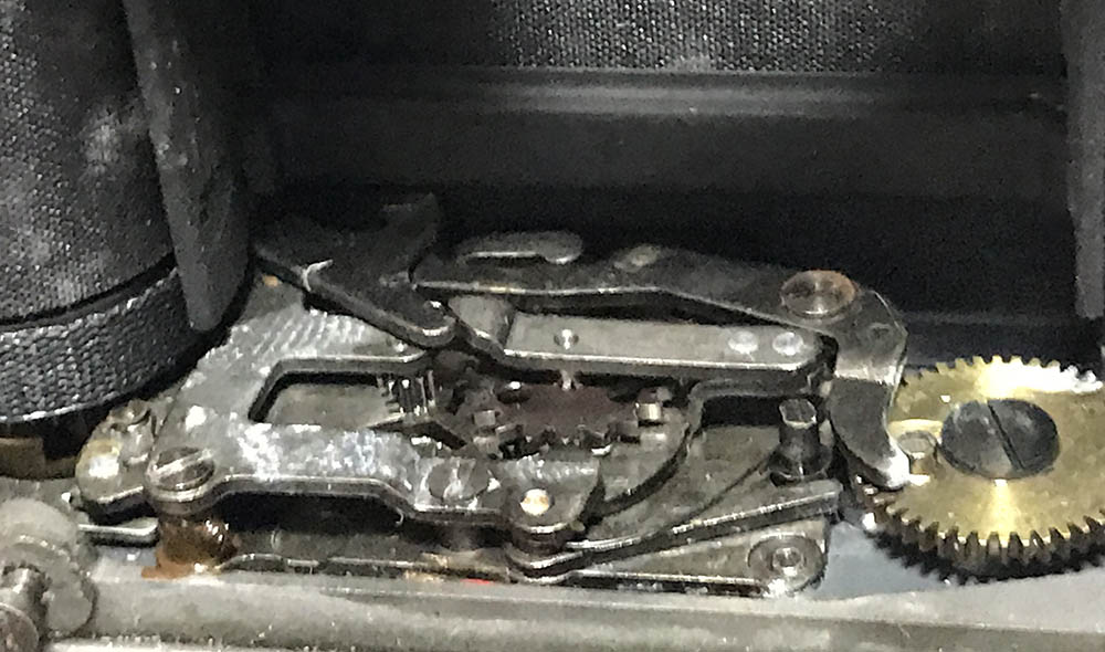
The ratchet mechanism looks clean on this one, oil and dirt can sometimes make this stuck so flushing it with solvents is beneficial. There are springs for the pawls and be sure not to dislodge them. A little bit of oil at the base of the pawls will help make it work smoothly and applying a very light film of grease on the tips of the pawls will help, too.
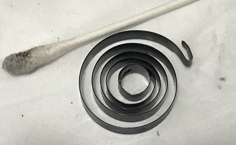
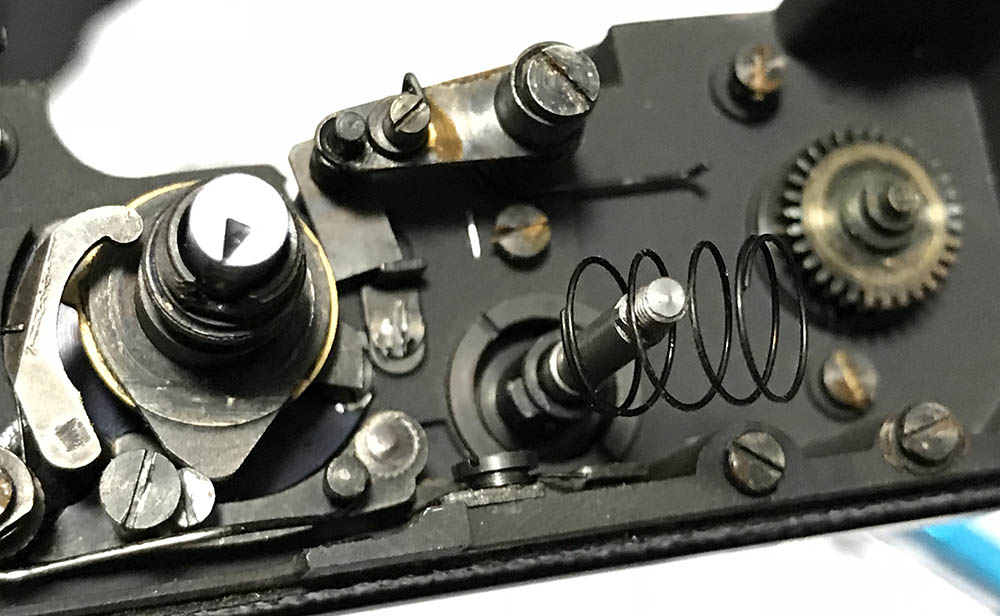
Cleaning the spring for the advance lever isn’t always required but if yours is dirty then the only way to clean it is to remove it. Make sure that the bent tip is safe and use a Q-tip saturated with solvent to clean it carefully.
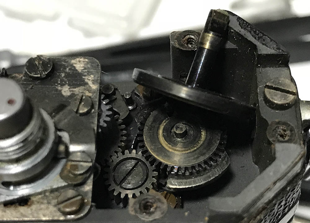
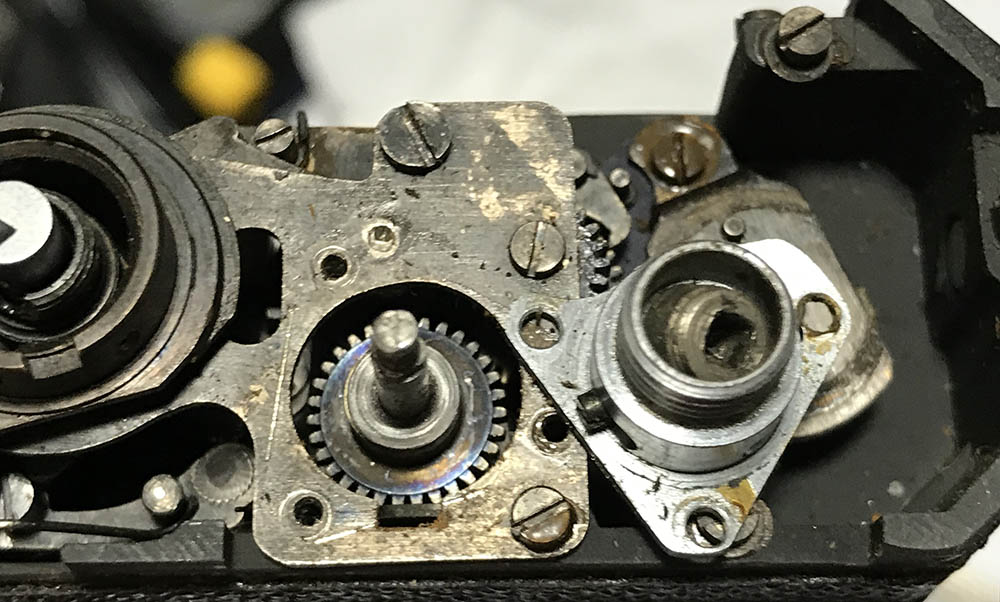
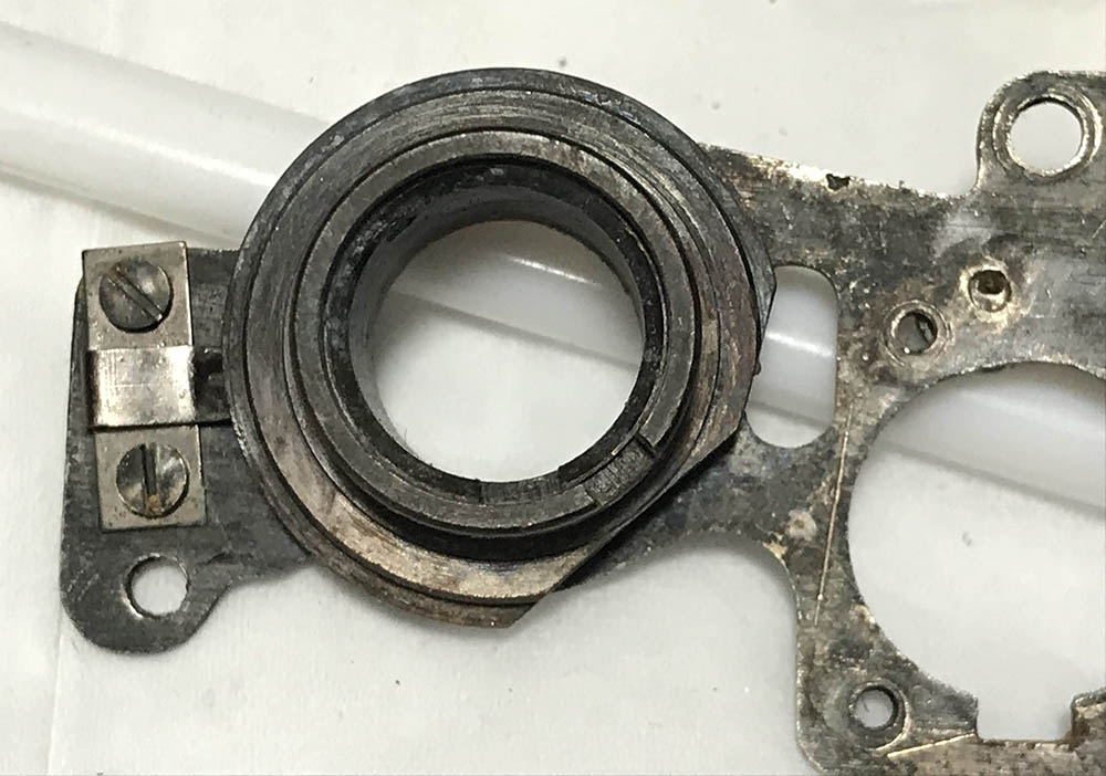
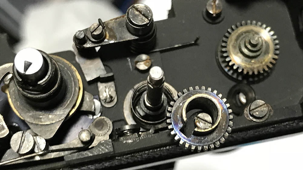
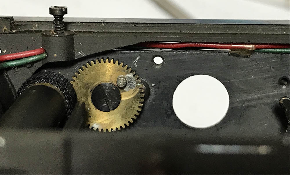
Remove the spindle of the film counter to reveal the eccentric underneath it and the cogs that turn it. These can get really dirty so clean them carefully.

Here’s a closer view of the gear train for the film counter mechanism. These are usually greased at the factory and that grease can get caked and end up making this mechanism feel rough. Note the position of everything, take all the pictures you need for your notes before you remove anything. The cogs for the eccentric pin can be easily removed.
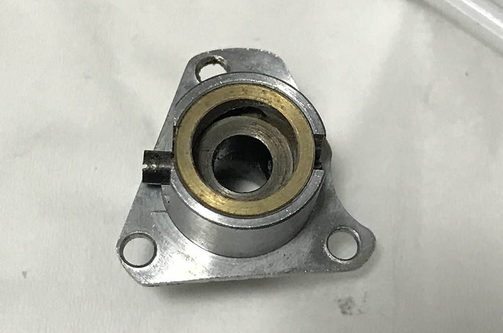
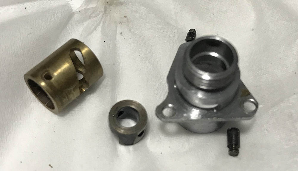
on to the bottom of the camera. Remove this cover to reveal a bushing.

Carefully remove it as it can be tight and make sure not to damage the inner hole.

This big screw secures the spool, carefully remove it using a long driver.

You can now remove the spool. It is merely suspended with the help of that screw that we removed in the previous step.

You don’t have to remove this because this part was adjusted at the factory so the spool aligns with the sprocket perfectly. The only reason to remove it is when you think that it’s jammed or damaged. It’s secured with this screw and removing it will allow you to unscrew it.
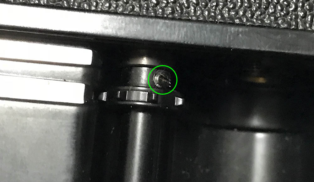
This screw helps align the film sprocket to the rod inside that also serves as the shaft for the shutter button so it can trigger the shutter by depressing a spring at the bottom of the camera. Removing it will allow you to apply a bit of oil inside or flush it with solvents with the help of a syringe.
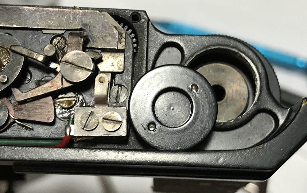
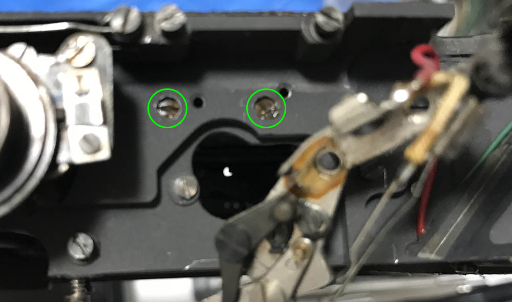
Let’s go back to the top. Extract these screws to remove the plunger and the A/R switch mechanism. This part can be adjusted so noting its position will help you later because it impede the movement of the A/R ring if this part is not positioned properly.
Unscrew the plunger button carefully using a rubber tool. You may have to hold the sprocket to help you remove this. Once this is gone you can easily remove the A/R switch mechanism.
There is a part inside that depresses the coupling gear and make sure that it safe since you don’t want to lose it.
Take plenty of notes before you dismantle the A/R switch mechanism. It can be difficult to put this back properly if you don’t know how it should align. I sometimes make a small mark to help me determine the cam’s position. The screws here aren’t identical, too.
This is how everything looks like once dismantled. All of these things should align properly or else the came inside won’t reach the coupling gear under it or this thing won’t turn properly at all. I always clean this part very well. I make sure that everything is squeaky-clean before I re-assemble it.
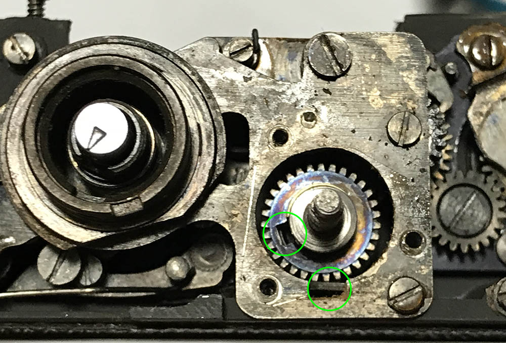
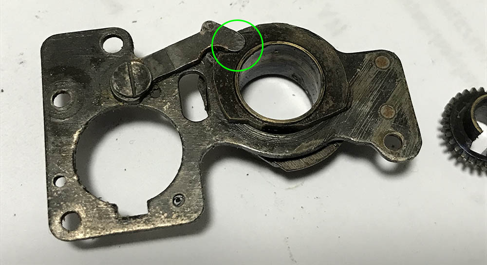
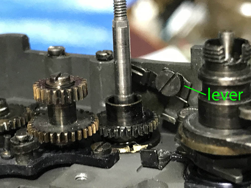
Unlike the Nikon F, the position of the coupling gear isn’t as important but it should be put-back the way you found it so note its position if the shutter is cocked. On the Nikon F, this cog also charges the mirror’s spring and you’ll have to make sure that its position is perfect. Note that there is a notch here that allows it to turn the shaft of the plunger so it can turn the sprocket. It’s important that you note this position when the shutter is cocked. There is a notch at the 6:00 position of its access hole and there’s a lever there. Note its position, too. Depressing this will push the main cog for the shutter down so the shutter trips when you turn the A/R ring to the rewind position.
Remove these screws so you can remove the top cover. Do not forget to take plenty of notes since these screws aren’t identical and they should go back in their respective holes. Some of them have bigger heads while some have longer shafts. Putting them in the wrong hole is just asking for trouble.

Carefully pull the arm of the curtain release lever so it won’t gat caught. The arm can easily be warped if you’re not careful. It’s best to keep an eye on it while you remove the top cover. You can slide to top cover and find a good angle so you can clear it. Damaging this is something that you should avoid at all cost.
This is the slow-speed regulator, it regulates how deep the slow-speed lever should be and that affects how much it’s being pushed by the spinning hook of the closing lever. The more it’s pushed, the more energy it will give to the retarder or slow-speed governor. That charges the spring of the retarder so it will delay the action of the closing curtain depending on how much it has been charged. The position of the tongue here in relation to the depression on the cam of the slow-speed selector dial’s cam is how it should be when it is at its slowest speed of 1s.
This is how things should align.

You can dismantle it further after removing a few set screws. Don’t forget to align these perfectly later.
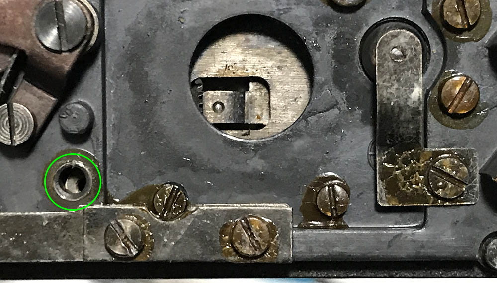
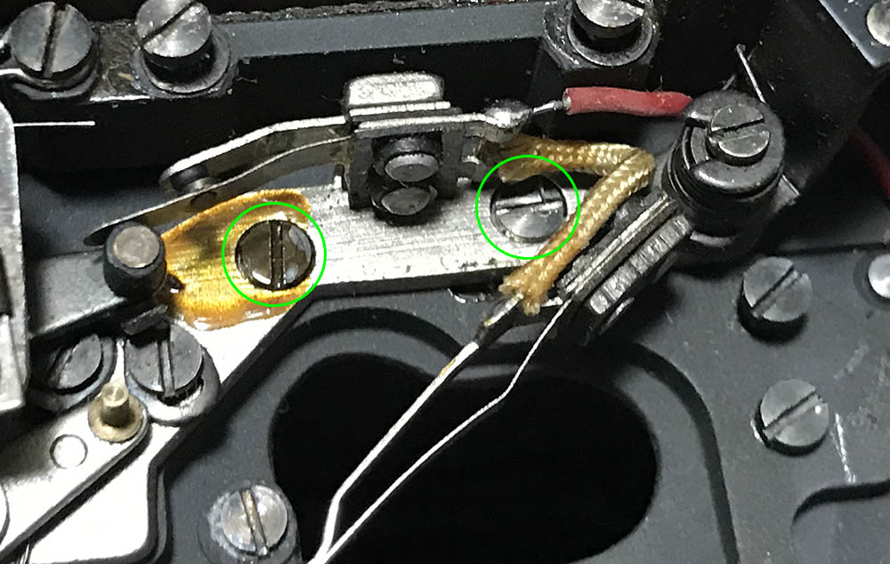
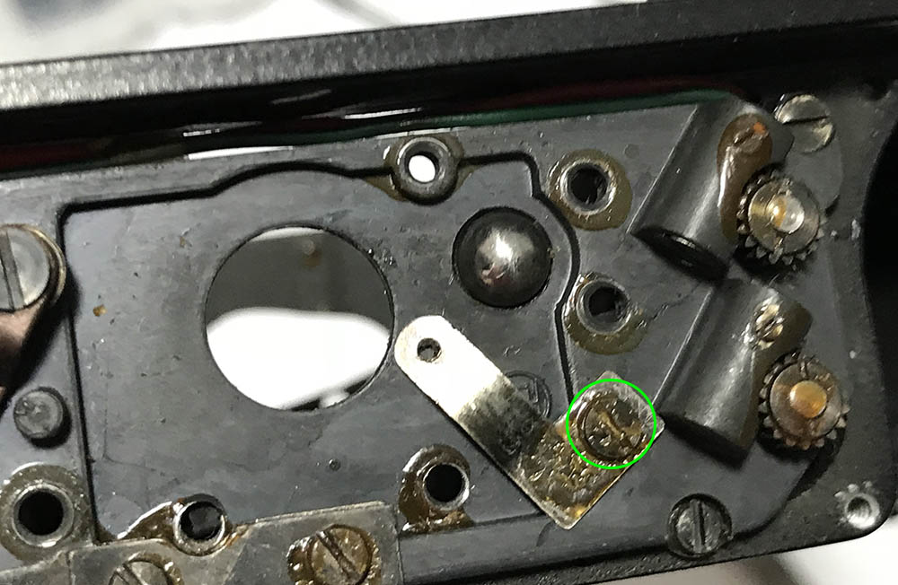
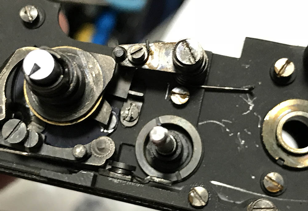
This is the perfect time to take notes and study how things work. This is the spring of the slow-speed lever and its pawl. The spring ensures that this will always be depressed against the slow-speed regulator. Look closely and you will notice that the pawl is resting against a flat post. This is the position for the T setting. Turning the slow-speed selector dial will dislodge this so it will continue to turn and activate the closing curtain. Encircled in this picture is the adjuster for the slow-speeds, this is an eccentric and it adjusts how deep the slow-speed lever should go. This is where you adjust speeds from 1/2s to T but it will also affect 1/4s somewhat. The small screw to the left of the end of the spring where it rests is another eccentric and turning this will allow you to adjust speeds from 1/8s to 1/30s. These all affect each other to a small extent and they are somewhat dependent on each other so adjusting one of them will affect the other one’s results in small ways.
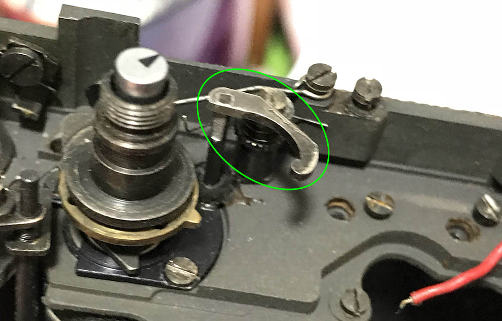
This lever will raise the charging gear of shutter when it’s depressed. There is a spring connected to it that ensures that it stays up.
Here is another view of that lever. Note its position and that of its sprint. It’s a very important part so make sure you don’t damage this.
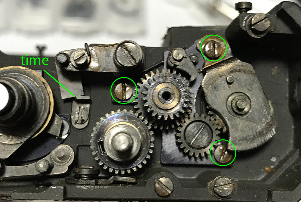
Time to go back to removing things. Unscrew these to remove the gear train of the advance and film counter mechanisms. It’s an assembly and it can be removed as a single unit. This is also adjustable just like the A/R mechanism so note its position. If this isn’t positioned properly your advance lever will not turn smoothly or the film counter won’t turn evenly. It’s also easy to see the position of the slow-speed lever in this picture, it’s set to T (time) here. If your shutter won’t stay open when set to T then you should adjust the post. I rarely have the need to do this.

Here’s how the whole assembly comes off.
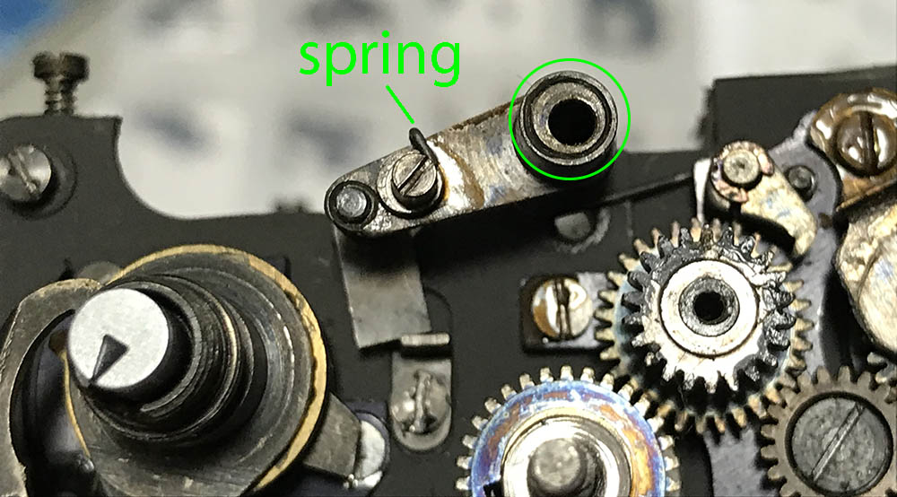
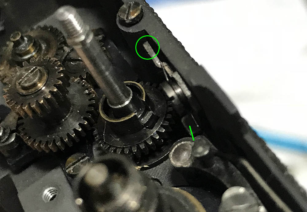
There is a hook on the end of a spring in one of the cogs, this pulls the pawl when it’s turned the other way. This way, the advance lever won’t and all of the cogs won’t re-set before the shutter is cocked and will allow you to cock the shutter in increments. This spring can easily be lost so be careful. Do not lose anything here and take plenty of notes on how things should be aligned or where each and every part is positioned, that includes the washers.
The coupling gear can be easily removed. It links the shutter-charging gear to the film advance gear train when it’s depressed and it de-couples them in the R mode when this gear is raised, effectively removing the link. This is a very clever mechanism as it’s both simple and reliable and the only way it’s going to fail is when it’s jammed due to dirt.
Don’t lose this spring under the coupling gear or it won’t work properly. The spring ensures that it will rise when the A/R switch is turned to R. This also suspends the coupling gear in-place so losing it will result in a shutter that’s never going to cock properly or allow it to rewind.

This is the driving gear of the spool. Clean it very well along with its hole. It can be filled with grime which makes it turn in a rough manner. I always do a thorough job on this and grease it properly before I re-install it.
Clean everything properly and flush them with naphtha to remove any dirt or oil. As somebody who grew up in a watch repair shop, I tend to do what our employees did when overhauling watches so I soak any mechanisms in a small dish full of toluene or other non-polar solvents. This is toxic but this is essential if you ask me, this will dissolve any stubborn dirt and can even remove light corrosion and stains. Terrible corrosion can be addressed by a quick soak in a weak solution of citric acid and distilled water. This process should never exceed more than 10 minutes or else the citric acid will eat at the metal. This is dependent on how strong the mix is, brushing with a tiny brush will help speed-up the process, too. I do this half-way into the process where the corrosion is softened by the acid. Flush and clean the parts with a nice bath of fresh water and rinse it very well, you’ll want to do this several times to make sure that no acid remains in your parts. Finish it by soaking your parts in solvents. If the acid ate-away at the patina and you ended up with shiny bare-brass parts then you can blacken them using an oxidizing agent. One good brand is “Blackey“, this is a blue liquid that turns brass into a nice, dark tone. The patina helps prevent corrosion but Blackey is hard to source and is never cheap.
Disassembly (Timing Mechanisms):
This section deals with some of the timing mechanisms of the shutter. Don’t treat this as a complete guide, I left-out some important things here because I don’t want beginners tinkering and ruining their cameras. I’ll only discuss important things in short, simple commentaries mostly pertaining to how a mechanism works. I may have forgotten some things and I may even give a part the wrong name or description so please bear with me. I haven’t done any camera repairs for some time due to the busy nature of my job.
Like the previous section, you will want to take plenty of notes here to help you navigate through the process or note how things work. Even a video on how things work will help you a lot. Having said that, notes and photos are not going to be enough because you will have to re-adjust things later since these are precise machines and upsetting their alignment by even a bit will throw things out of sync. Pay attention on how gears mesh and you’ll even find yourself counting the teeth of a gear which is not unusual in this field. I will advise that you use a soft touch here when removing anything because some of the parts here will require you to push or pull something in order to allow it to pass-through without damaging anything. The parts here are delicate and should be treated with care and respect since these machines are now old, rare and valuable.
This is the retarder, it delays the action of the closing curtain depending on how much energy its spring stores. An escapement helps regulate how the energy is wasted so it won’t activate the closing curtain immediately. This is usually the culprit when a mechanical camera has bad slow-speeds. A dirty mechanism can be jammed, it can also cause problems when it’s not aligned properly or any of its delicate parts are damaged.

The retarder is being secured by these screws and another one that I forgot to encircle but I may be wrong.
The retarder can be adjusted so take plenty of pictures before you remove it so you’ll know hot to put it back. If your slow-speeds are off then make sure that this is mechanism positioned as forward as possible towards the front of the camera. It can’t be moved much but it’s better than nothing.
Carefully remove the retarder and make sure that it doesn’t catch anything. You may have to press on the change-over lever to free this. One important thing that I should note is you have to be careful when removing this since the coupling fork of the slow-speed shaft is connected to this, you can see it in this picture just below the drum of the closing curtain.
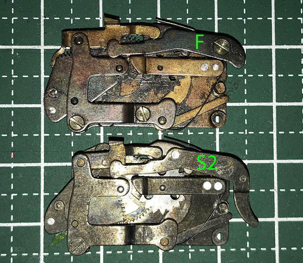
For those who find this mechanism familiar, it’s the early version of the one found inside a Nikon SP and the Nikon F that was based from it. While they are similar, they don’t share many common parts.
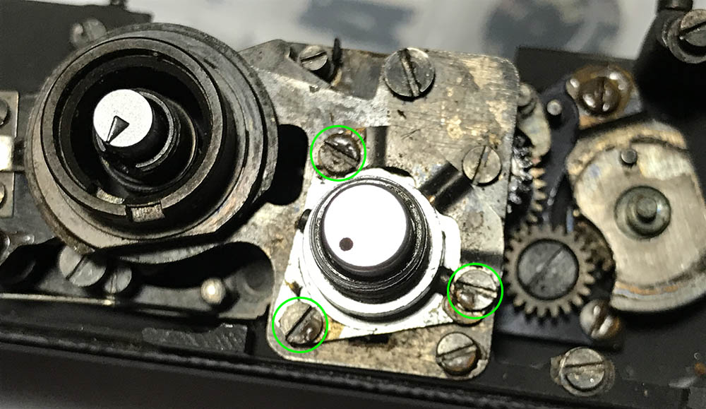
Removing the flash sync mechanism is easy once these screws are gone. The seals have to be removed first with solvent if yours is stuck.

This is the change-over lever, it regulates how low the yoke of the retarder should be. The lower it is, the more the escapement engages the escapement wheel of the retarder. It’s controlled by an arm at the other end, connected to the slow-speed selector cam of the slow-speed selector dial.
The orientation of this gear is important, take plenty of notes and photos of it specially if the shutter is in the cocked position. You don’t have to remove it but it will benefit from a thorough cleaning if yours is dirty.
The baffle is secured by 4 screws and here’s 2 of them (removed). There are 2 kinds of baffles for the Nikon S2, earlier ones come in several pieces while the later one was cast as a single piece which feels flimsy in my opinion.
Here’s the other 2.
The late type baffle can be difficult to extract and it can sometimes get bent in the process. You will have to depress the change-over lever slightly, make sure that you don’t warp it because adjusting it is a pain. The best angle for removing the baffle is sliding it this way.
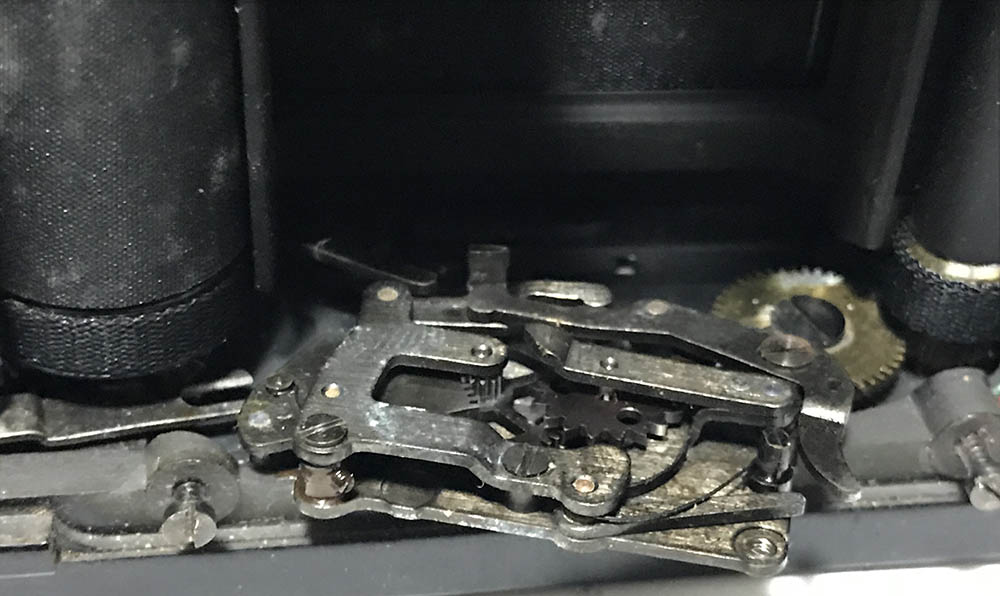
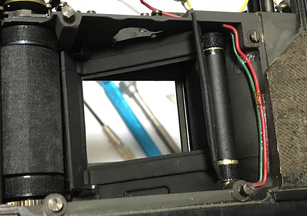
This is the break for the front curtain. This is unique to the Nikon S2, and it’s very effective at preventing the front curtain from rebounding. It makes an audible “click” when the pin of the front curtain’s gear passes under it. This makes the sound of the Nikon S2‘s shutter unique. It can be noisy at times, I don’t get bothered by it but it was enough for Nikon to develop a quieter one for their next camera, nick-named the “whispering shutter“.
Study how things work. It’s easy to see how the opening curtain’s pawl hits the high-speeds lever. It’s the boat-shaped lever to the lower-left part of the frame with 2 eccentric screws attached. These 2 screws along with a smaller pin near the pivot adjusts the faster speeds from 1/125s up. The 2 eccentrics can be adjusted which allows for small corrections but it’s a lot better than having none at all. Adjusting this is tricky so only leave this for the expert. It triggers the closing curtain depending on how much the tip of the opening curtain’s pawl’s hits it and the 3 pins adjust how much of it touches the pawl of the opening curtain as it spins to finish the opening curtain’s cycle.

Loosen this screw to remove the change-over lever from its shaft but take a lot of notes before you do so because this can be tricky to adjust. I wanted to remove this because I needed more space for replacing the shutter but this is best left alone.
You can now pull the change-over shaft and it’s claw off. Be sure to note any springs that are attached to anything in this area before you remove this or any part here.
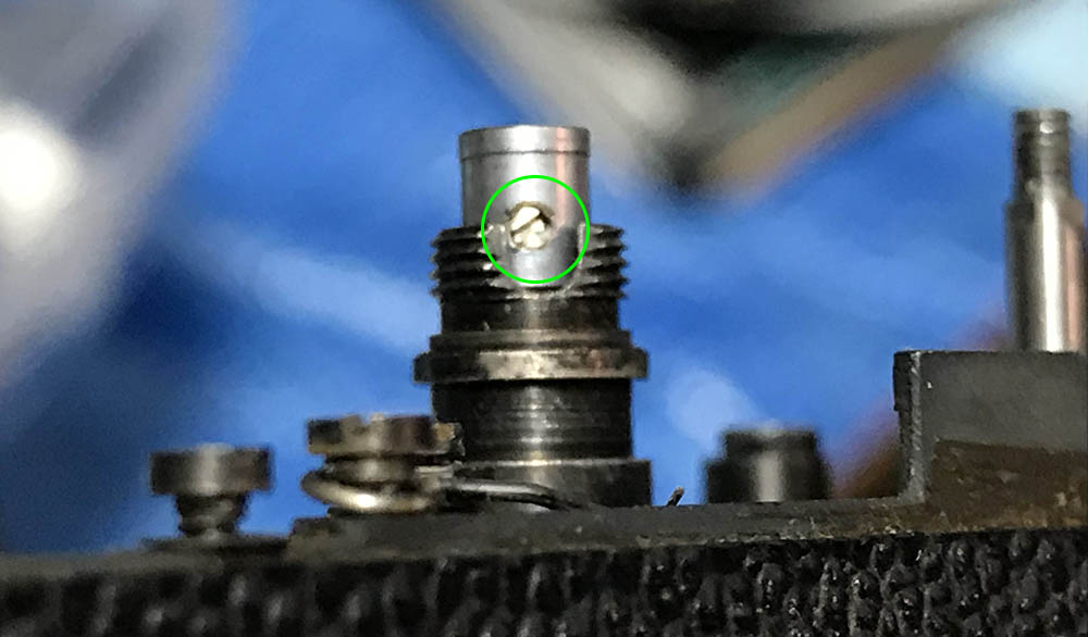
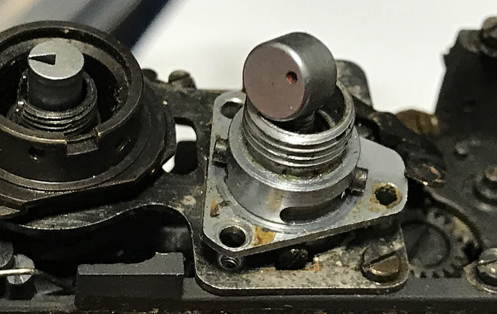
This is optional but I sometimes remove the spinning tip of the shutter’s rod to clean the cover and flush everything with solvents. Extract this screw to remove the cover and make sure to put it back properly, it should sink into a small depression on the rod or else the cover won’t be centered to the rod. This will cause it to touch the inner walls of the high-speed selector dial as it spins and that causes erratic fast shutter speeds which can be frustrating to trace.
The retarder should never be dismantled, even Nikon suggests replacing the whole assembly because these were tuned as a whole unit. Clean it by using solvents and flush it very well. While it was designed to run dry you can oil some of its pivots sparingly using the best watch repair oil you can source. I usually apply oil with the tip of a needle, this is enough and adding more is not necessary and can potentially be a problem as the oil can turn dirty and jam the anything. Be careful not to dislodge any springs, too.
Conclusion:
Clean everything very well and brush them if they’re not delicate to remove any dirt. Flush any delicate mechanisms and blow them dry using a blower. Make sure that you don’t lose any screws, springs or anything while doing it as some things are merely suspended by dirt. As a rule, oil any pivots if you think they need them. A small amount of oil goes a long way so never apply too much because that will only cause trouble later. Pawls, gears and other parts will benefit from a light film of grease on their teeth and tips. I used to apply molybdenum grease for metal-to-metal surfaces but I use silicon now since they’re better in the long run. Just like oil, never apply too much of it! You will also need different grades of grease, some light and some thick. It’s important to determine which parts will require what kind of grease, what I do is I apply thicker grease to parts that are operated with using the power of your hand such as the gear train of the film advance or the A/R switch. A light grease is best for things that operate using the power from springs and other sources that are powered by momentum such as the pawls. Applying a thin film of grease on the pawls will help them operate smoother because resistance is good way to waste kinetic energy. It’s safe to say that you only apply grease sparingly and only on parts that require it and the other parts are just fine with high-quality oil.
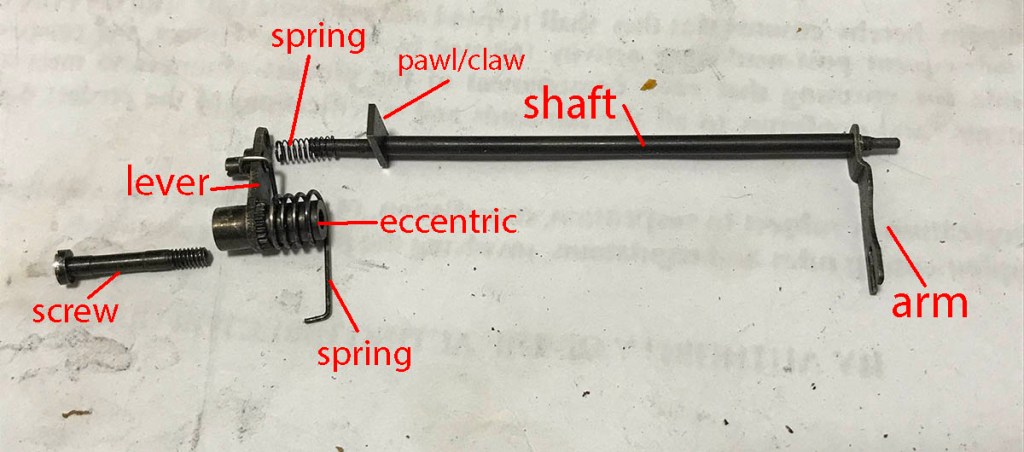
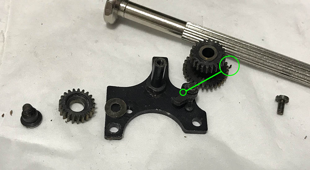
This is the slow-speed lever mechanism. Make sure that you don’t lose these parts, they may drop to the floor without you knowing! The screw is what’s used to secure this to the body casting and it’s connected to the eccentric. It can be adjusted by turning the knurled part to adjust for the slowest speeds. The spring makes sure that the slow-speed lever touches the regulator so its position changes depending on the position of the slow-speed regulator. The tiny spring on the top-end of the shaft suspends it so it will come-back to its position after the pawl of the closing curtain clears it. The slow-speed arm is a fork which engages the retarder and it transfers the energy from the pawl of the shutter and it charges the spring of the retarder.
This is a video on the Nikon F’s retarder. It’s different from the one we have here but they generally work the same so you can use this video to help you with getting to know how the retarder works.
Here’s a map of all the articles in this series so check these out so you won’t get confused with anything.
- Part 1 (Top & Front Panel)
- Part 2 (Internals & Rangefinder Mechanism)
- Part 3 (Film Advance, Speed Selector & Timing Mechanisms)
- Part 4 (Shutter Mechanism)
- Front Overhaul (Rangefinder Adjustment)
That’s it for part 3, I’m currently busy and also a bit sick due to the weather but I wanted to finish this since I know that many people are following this series. If you liked this, please support my work. That will help me pay the cost of maintaining this blog, since this is an image-heavy site I have to pay more for storage. Thank you very much, see you guys again next time. Ric.
Help Support this Blog:
Maintaining this blog requires money to operate. If you think that this site has helped you or you want to show your support by helping with the site’s upkeep, you can make a small donation to my paypal.com (richardHaw888@gmail.com). Money is not my prime motivation for this blog and I believe that I have enough to run this but you can help me make this site (and the companion facebook page) grow.
Leave me some tip?
Thank you very much for your continued support!
$2.00
Helping support this site will ensure that this will be kept going as long as I have the time and energy for this. I would appreciate it if you just leave out your name or details like your country’s name or other information so that the donations will totally be anonymous. This is a labor of love and I intend to keep it that way for as long as I can. Ric.

Sep 25, 2024 @ 23:07:07
Will camera still work if the spinning tip cover of the shutter rod is missing?
Thank you kindly
Tony Villaraza