
Hello, everybody! I’ve been granted permission to work-from-home due to the coronavirus pandemic. It is essential that every member of the team is synced to the main workflow seamlessly from home. This requires plenty of effort in the engineering side as data and communication needs to flow well despite people being scattered in multiple locations. This reminds me of the rangefinder cameras of old, it’s amazing how the rangefinder couple to the lens and how it can still accurately depict what’s going to be in-focus. That’s very clever considering that it was pioneered nearly a century ago. This is a complicated mechanism that links 3 things and that’s the topic of our article today.
Introduction:
The shutter-speed selector of the Nikon SP chassis is robust, the same goes for the Nikon S3 / Nikon S4 and the Nikon F, too. All of these share the same chassis except for the Nikon F which uses a modified one that will accept a mirror-box so it’s made wider. The shutter-speed selector mechanism is not a new design entirely, it inherits a lot from the older Nikon S2 as the basis. It is not identical yet not too-different either in principle and you can see their similarities once you get to know how they both work. Despite that, this is a big leap for the Japanese camera industry, the shutter-speed mechanism is a modern one wherein you can change every speed of the camera using one convenient dial. I am not aware of any Japanese camera that can do this at the time the Nikon SP debuted since most, if not all Japanese cameras used the Leica-type shutter (as far as 35mm goes).
The W-Nikkor 3.5cm f/3.5 is a good partner for the Nikon S3, it balances very well with the camera and the 35mm frame-lines help you frame with it. You won’t need a separate accessory just to frame your shot.
The freedom of having a single dial to change your speed give you freedom to use your other hand for something else such as focusing the lens. This is something that every Nikon S2 user will enjoy. It sounds silly because we’re spoiled these days with fancy cameras but this is something special back in 1950s Japan. We can’t live without it these days, only people who enjoy the whole process of using a classic camera will enjoy using one that requires you to adjust 2 separate dials just to get the right shutter speed. It is fine for hobbyists but professionals demand something more efficient.
In the first part we talked about how to dismantle the top panel. Part two is a bit more complicated as we cover the front panel. We’re now going to see more intricate parts as we discuss how to dismantle the upper mechanisms. This is not something for the amateur to do, you will need special tools and a lot of experience to successfully pull this off. Your camera is best serviced by a reputable repairer. There are many cheats out there so you will have to do your homework if you want to look for the real-deal. Don’t rush, it’s best to take your time and wait for the right repairer to service your camera. Do not use this as a repair manual since I am just sharing my repair notes. This is only meant for your entertainment and education. Experienced repairers will find this useful if they’re not familiar with Nikon rangefinder cameras, it helps them prepare so they won’t find any surprises when working with one.
Before We Begin:
If this is your first attempt at repairing a lens then I suggest that you check my previous posts regarding screws & drivers, grease and other things. Also read what I wrote about the tools that you’ll need to fix your Nikkors.
I suggest that you read these primers before you begin (for beginners):
Reading these primers should lessen the chance of ruining your lens if you are a novice. Before opening up any lens, always look for other people who have done so in Youtube or the internet. Information is scarce, vague and scattered (that is why I started this) but you can still find some information if you search carefully.
I highly recommend that you read my working with helicoids post because this is very important and getting it wrong can ruin your day. If I can force you to read this, I would. It is that important!
For more advanced topics, you can read my fungus removal post as a start. This post has a lot of useful information and it will be beneficial for you to read this.
Disassembly (Upper Mechanisms):
This is going to take most of your time in terms of disassembly but once you get to this point you’re probably half-way through the overhaul. Needless to say, once you’ve gotten here there’s no more looking back. Most, if not all of the bigger screws here were sealed with lacquer or contact cement and you will need to apply solvents or heat to safely extract them. Be very careful if you use them as you don’t want to flood or damage anything.
Take as many notes as you can so you’ll know how to put things back again, failure to do so will result in inaccurate operation of the camera. This is not something that a beginner should do, leave this to the professional. You will need special tools to open or extract things here. Experience is also needed, that will help you make good judgement calls when you’re faced with hard decisions as you find irregularities in the repair process.
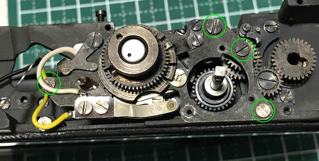
Carefully extract these so you won’t strip or snap their heads. Alcohol helps a lot in dissolving the glue used to seal these.
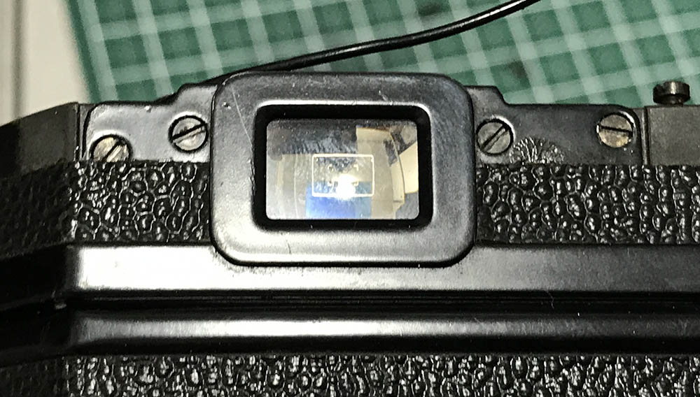
Be sure not to damage the viewfinder block and its magnifier.
The hot-shoe can be removed after you extract this. You have removed the 2 other screws at the front, this is the only 1 left.
Be careful not to crack the insulator when you remove it. I usually remove these so the contacts are safe and I can clean the hot-shoe better.
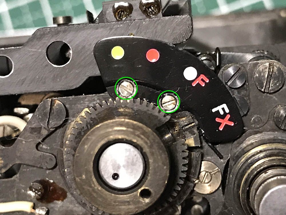
The flash-sync timing display is secured by these.
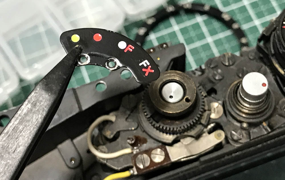
This is a very delicate part so handle it carefully. It’s made of thin metal and you can warp it easily.
The viewfinder is secured by a few screws, some of which are hidden.
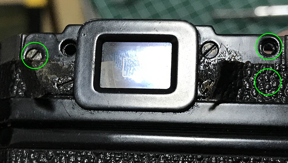
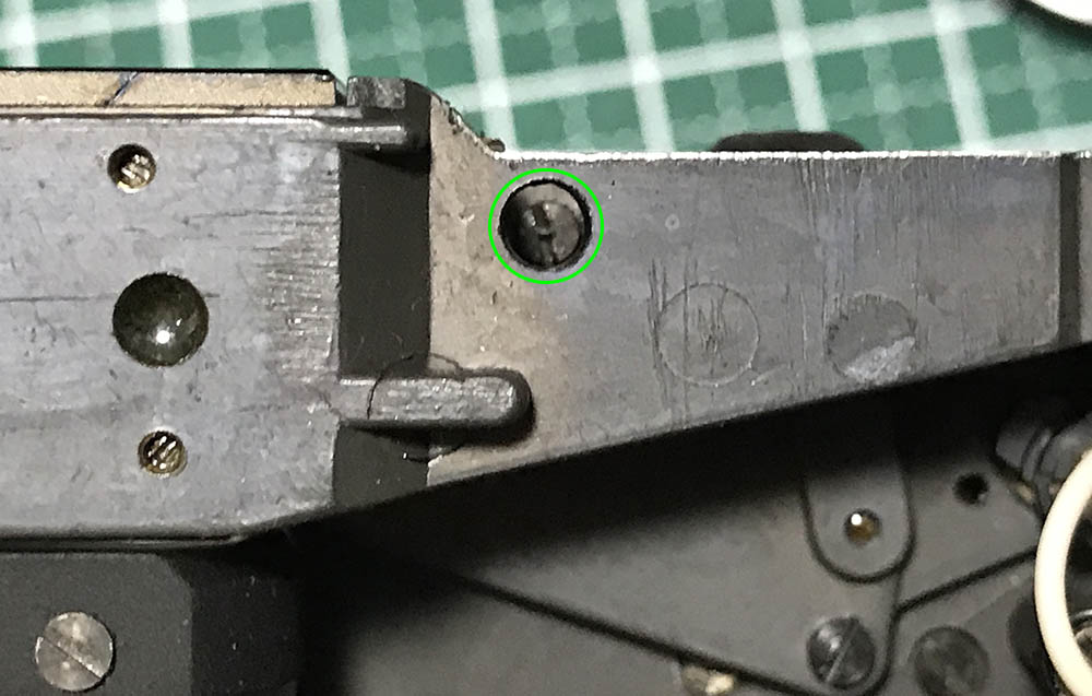
You’ll have to lift the old leatherette in order to access the other screws. The left-most screw can be tricky to remove, see the next panel to know why.
This one is the most difficult to remove because there’s a nut behind it. This secured the flash-sync’s ground connection.
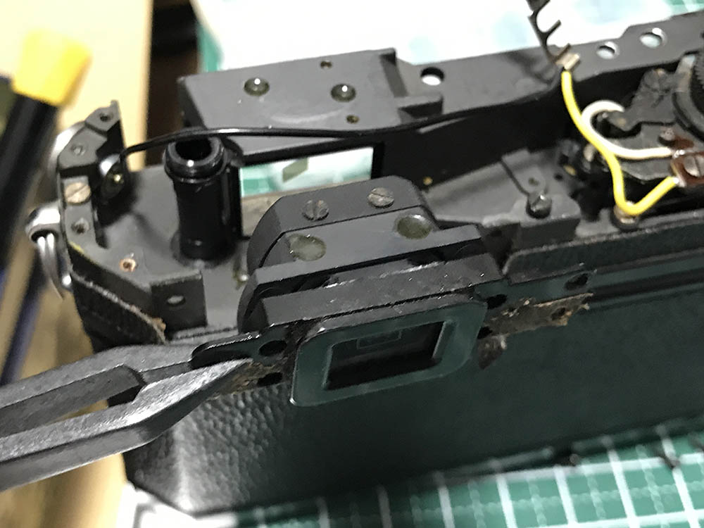
Carefully remove the viewfinder block assembly from the chassis.
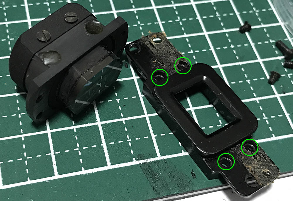
The viewfinder block is secured to eyepiece by these screws. Do not further disassemble the viewfinder block, there’s nothing to gain from doing it.
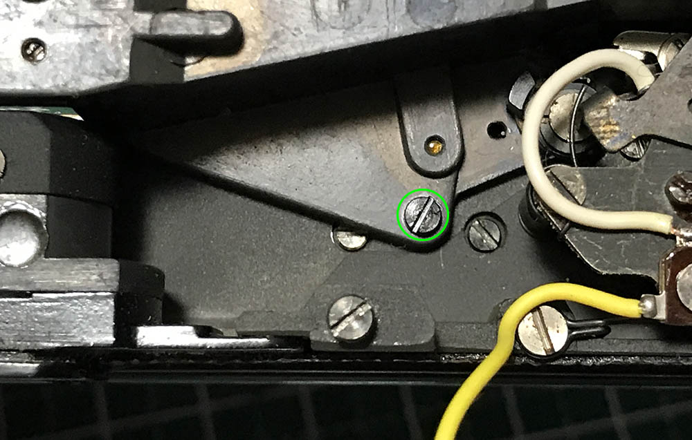
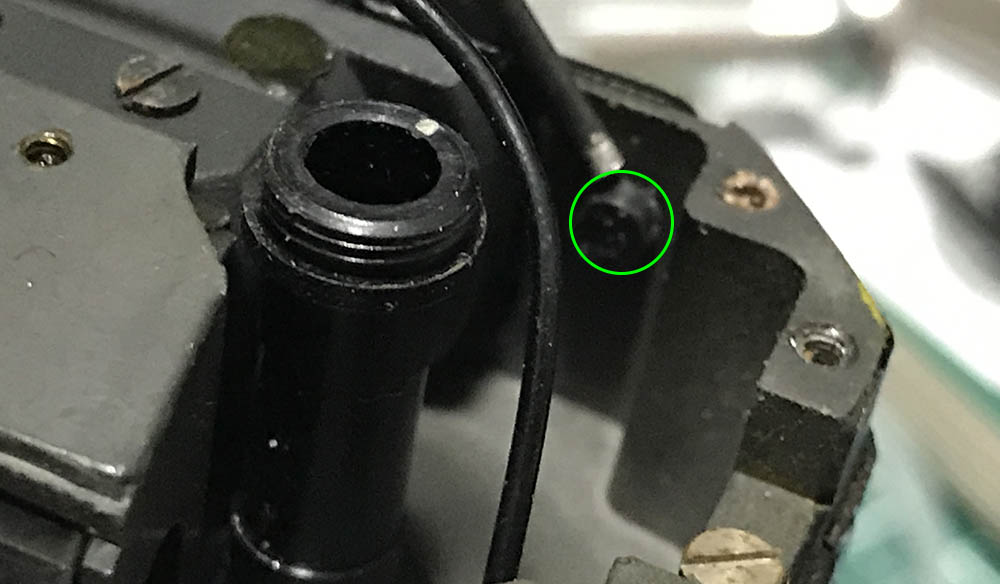
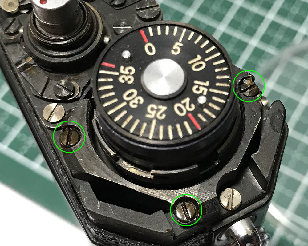
The rangefinder mechanism is secured by a couple of screws and this is one of them, carefully extract this.
Carefully extract this screw, you don’t want to disturb the rangefinder or its alignment.
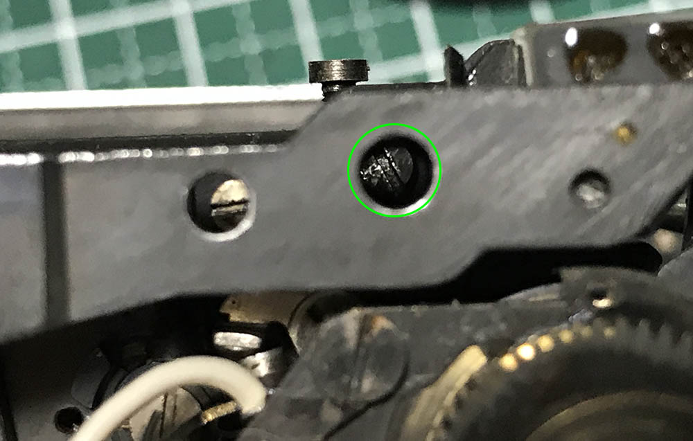
Extract this one, too.
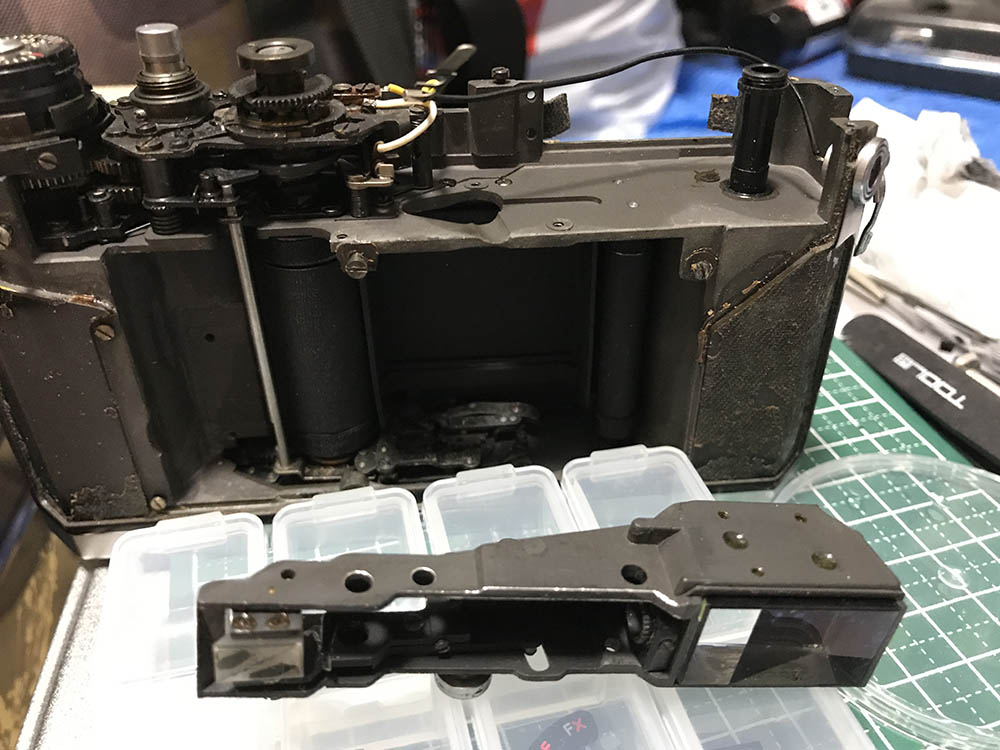
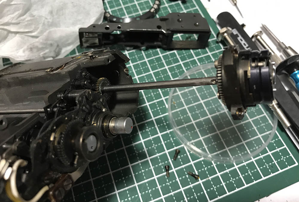
Carefully depress the rangefinder lever and slowly remove the rangefinder assembly. Make sure that nothing gets caught as you remove it.
These were sealed really well, apply some MEK and leave it for some time, I usually do this several times just to make sure. A soldering bolt helps, too. If you don’t have a driver that fits these perfectly then it’s time that you make one specially for these.
The film-counter mechanism can be removed by pulling it from the chassis. Its long spindle runs deep, you’ll have to pull it slowly in order not to harm anything.
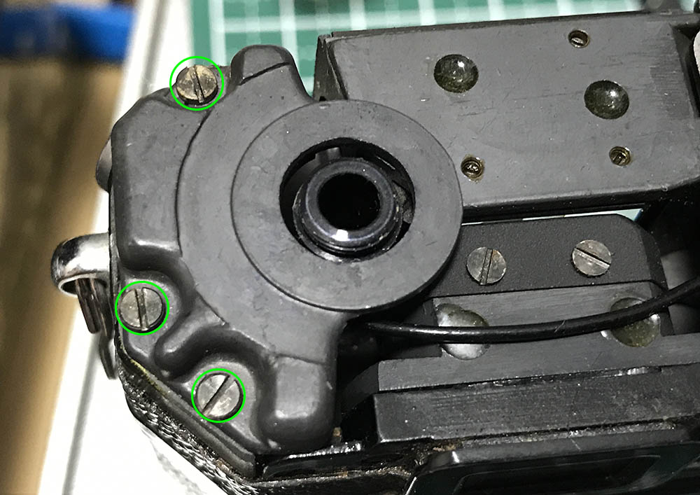
Remove the spring-lock by extracting its screws, there are 2 on either side.
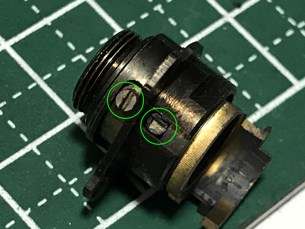
Turn the spring-loaded housing of the film-counter mechanism to see these. Extract these one-by-one, I think there are 3 of these if I am correct.
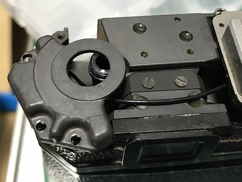
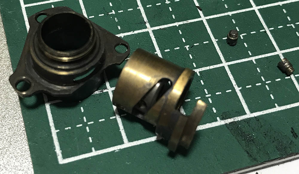
You can now separate the film-counter dial mechanism from the housing.
Everything won’t separate cleanly at this point because there’s a few things that you should uncouple, that will take a few more steps.
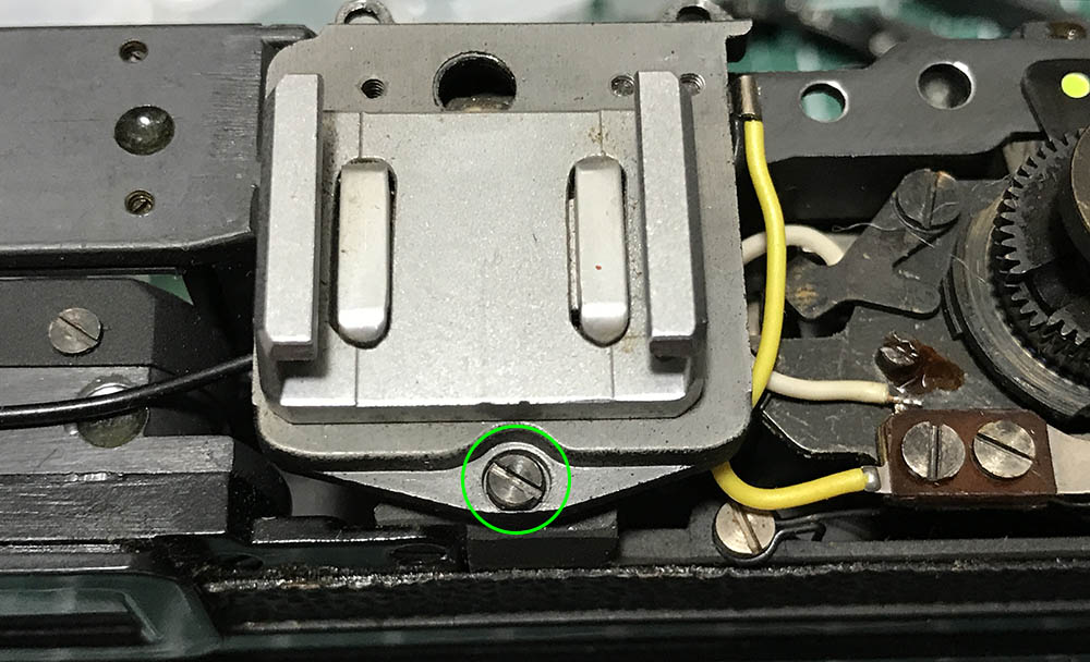
This screw is tricky to remove because the film-counter dial is above it. You will be able to remove it by using a small screwdriver, go slowly at it until it is loose then slowly turn it until it’s gone.
This is what you should have after. Be careful not to lose any parts here. It’s easy to loose the tiny bits here and it’s going to be difficult to fabricate them without the proper equipment.
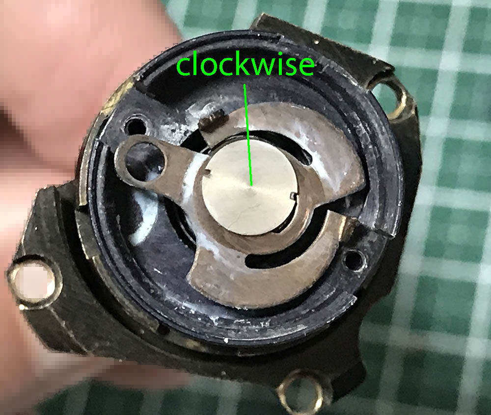
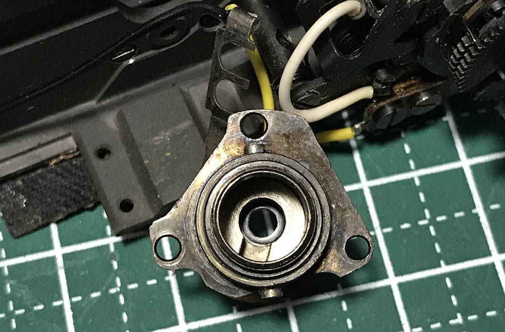
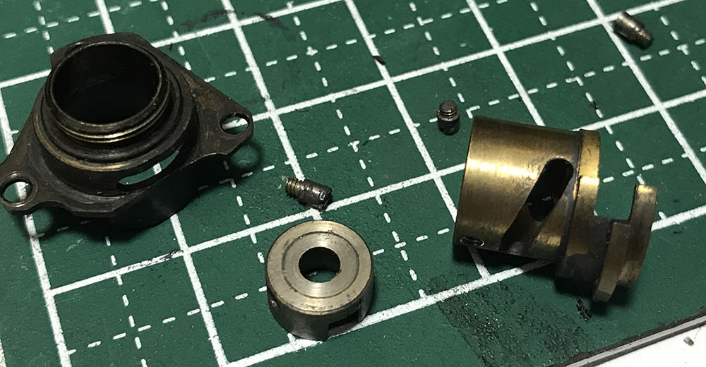
You will need a special tool to remove this. It’s a right-handed thread and it can be difficult to remove so I always heat this with a torch or pickle this in an alcohol bath. Turn this clockwise to loosen it and make sure not to strip the 2 small slots. That complicated part it secures acts like an escapement, it advances the film counter each time it goes-through a cycle.
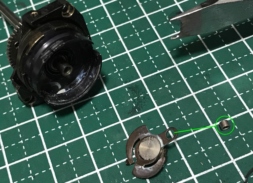
This small tube does into that hole, by the way. It guides the film-counter so it won’t wiggle as the escapement moves. That nut that we just removed is also the main thing keeping the whole assembly together, the spindle can be removed and the whole assembly taken-apart to its bare-parts now.
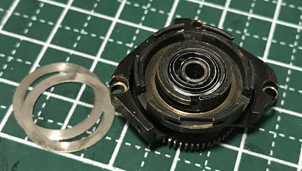
There are 2 shims here, never lose any of these. These ensure that the film counter dial won’t hit its external housing but still maintain its height so it’s not going to allow large pieces of debris from getting into the mechanism.
The shutter button can be easily removed.
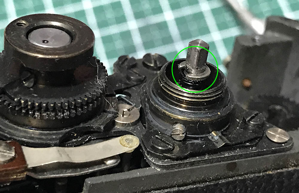
The spindle for the shutter button is being secured by this C-clip.
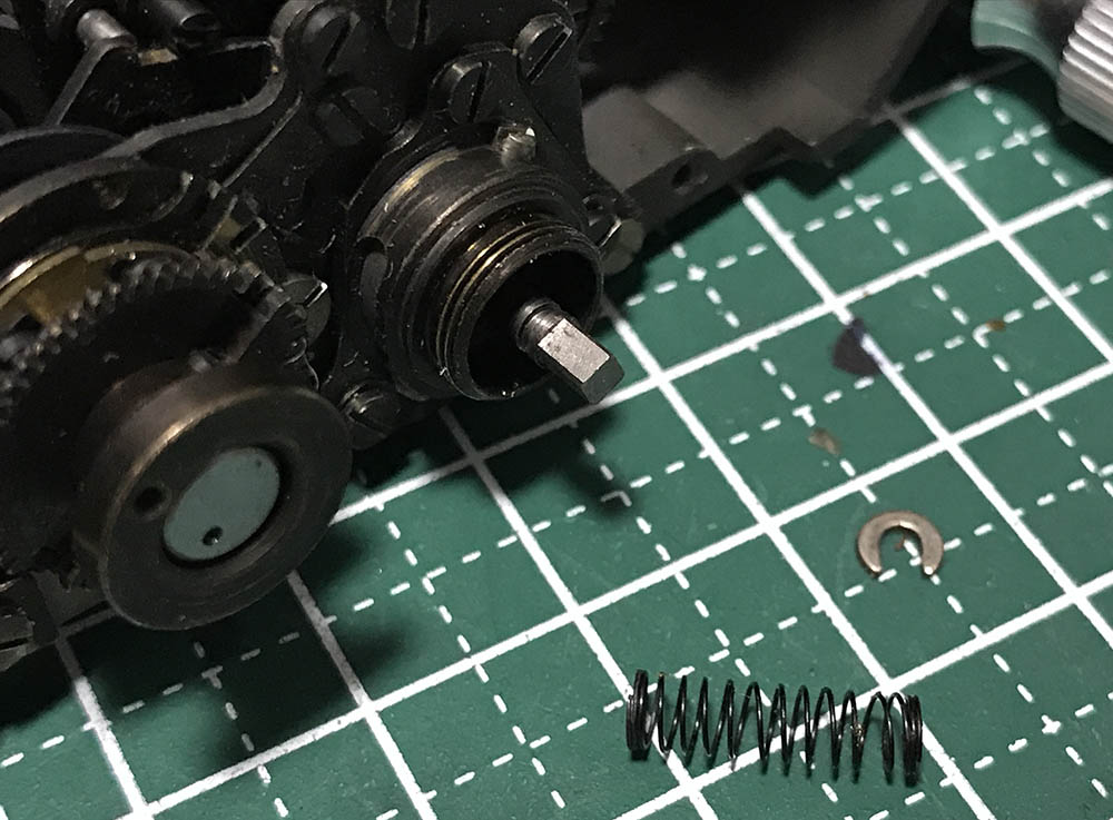
Carefully remove the C-clip and you can remove this spring. You may find a washer underneath the spring, don’t lose it.
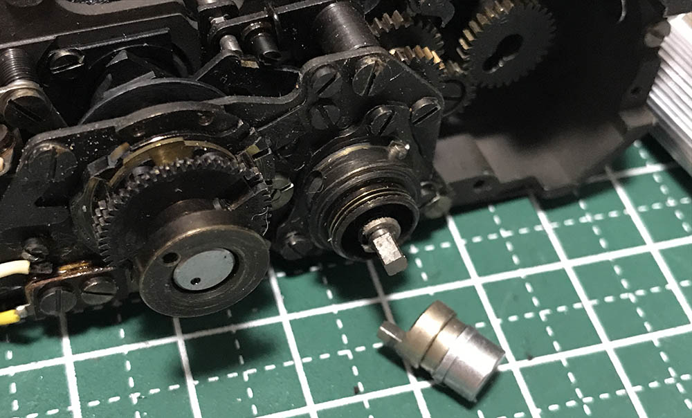
The A/R mechanism is being secured by these. Extract these carefully, don’t forget to take a photo so you’ll know where things should be oriented. There is a cam inside of this and you should put that back together facing the right direction when you disassemble it.
Make sure that you don’t lose anything when you remove it, you may find a washer or 2 around the shutter button’s rod.
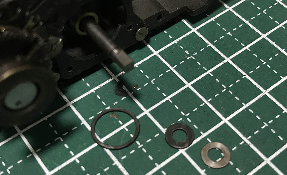
Here are the washers that I was talking about.
This is the proper alignment of the cam. Notice that there is a small washer inside of it.
There are screws that you should extract to disassemble the mechanism. It’s important to remember that these screws aren’t identical, some are longer while some are short so don’t forget to take notes so you’ll know which one should go where.
The cam is usually filthy due to decades-old grime. Clean it very well so you can turn this smoothly.
Here’s everything in this assembly.
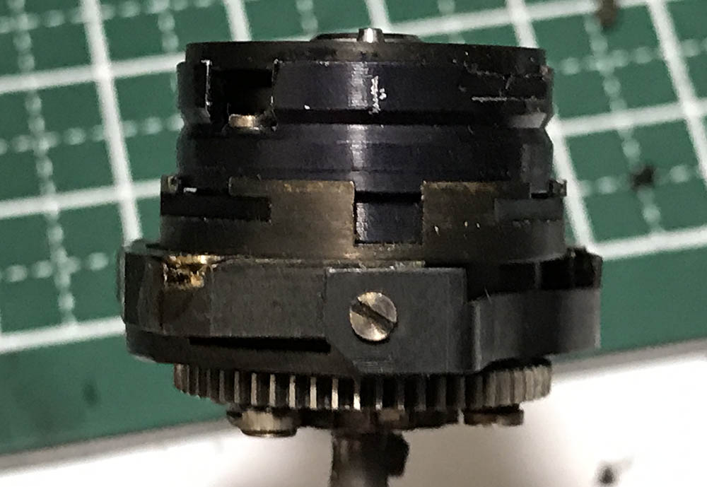
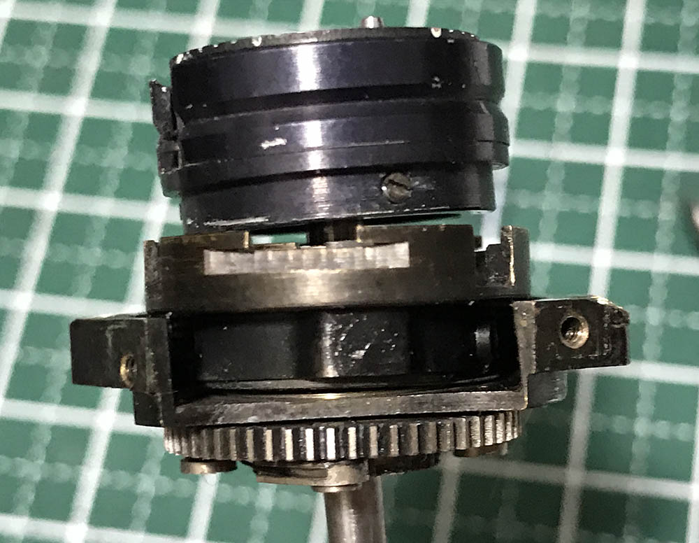
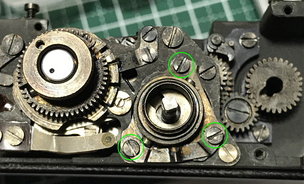
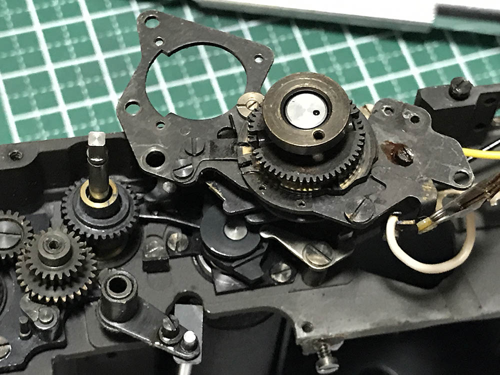
The speed selector assembly is tricky to remove but not as tricky as the one found on the Nikon F. Carefully extract these and don’t forget to take notes, these are all unique and the speed selector assembly won’t sit-flat if you’re not careful with their placements.
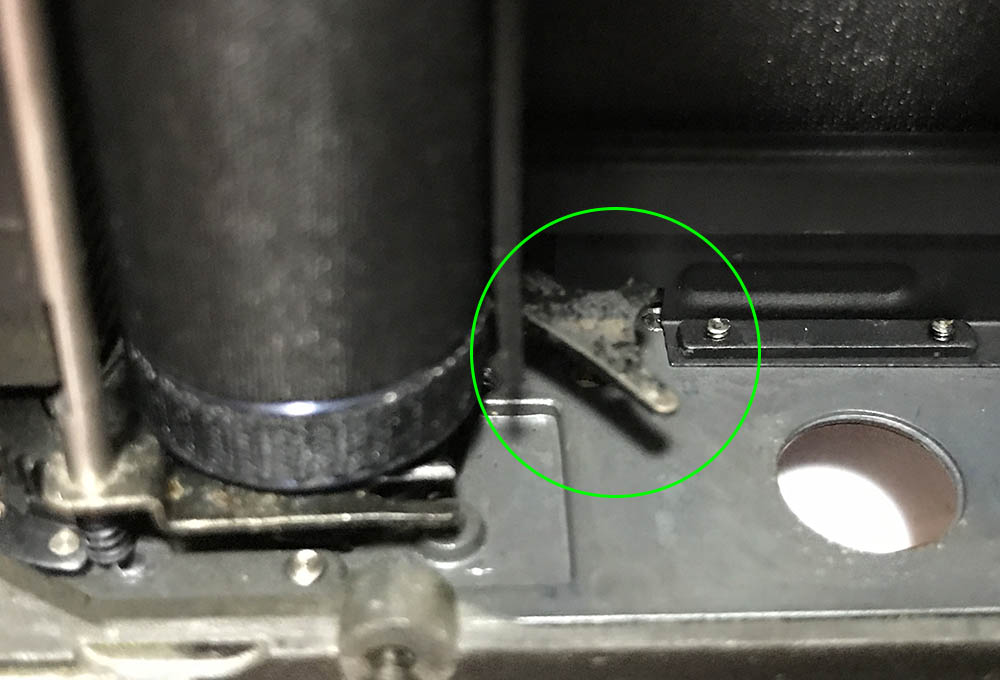
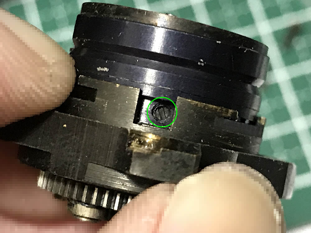
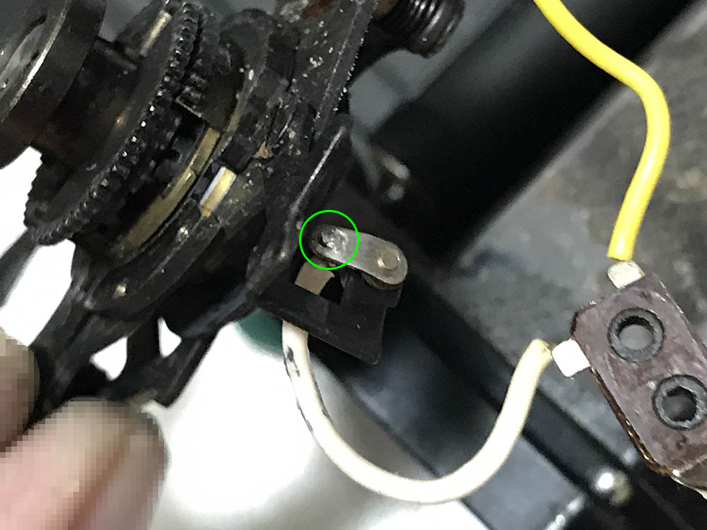
Before you remove the speed selector assembly, be sure to depress this, it is the change-over lever and it’s easy to bend this. The same goes for the other end, damaging either part will result in inaccurate slow speeds.
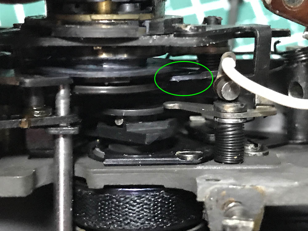
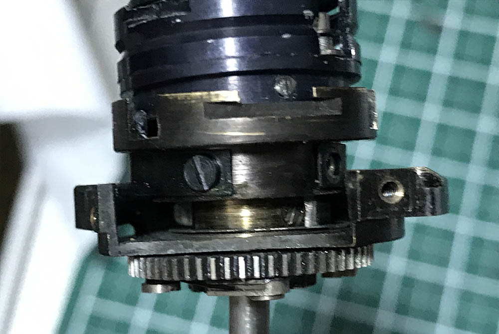
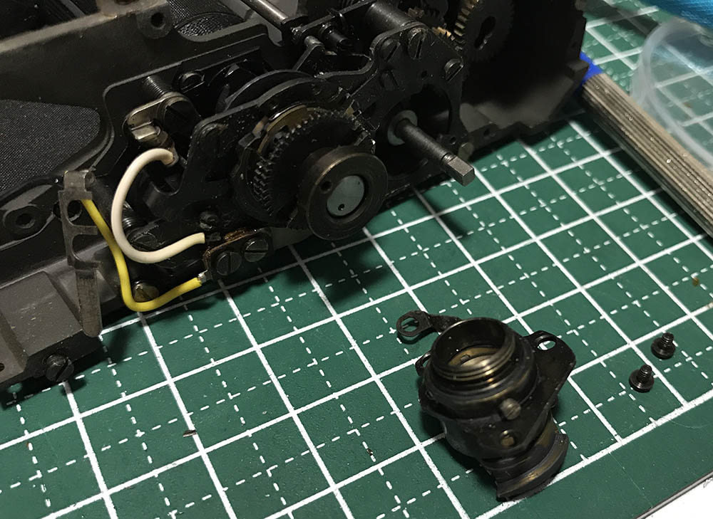
Depressing the change-over lever will disengage or at least lift this arm. It’s now safe to remove the speed-selector assembly. You must remove it slowly so you won’t damage anything, you can’t simply pull the assembly off, you’ll have to wiggle, maneuver your way to safely remove it.
Here it is now, you can now clean everything properly. Be careful when you handle this, damaging anything will result in inaccurate speeds, from slow to the faster ones.
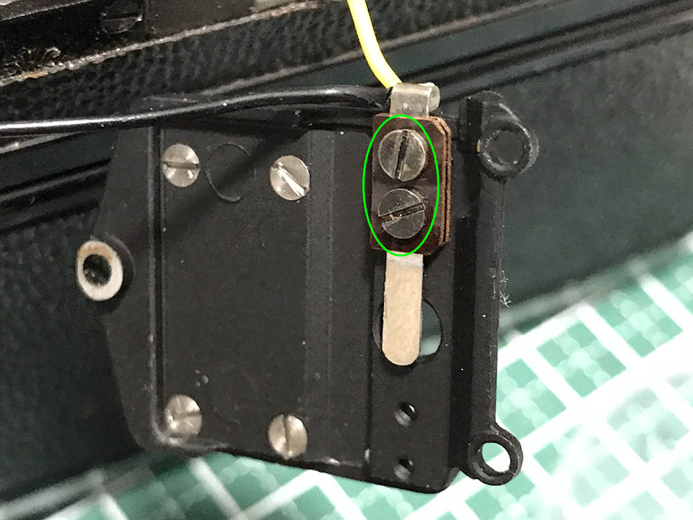
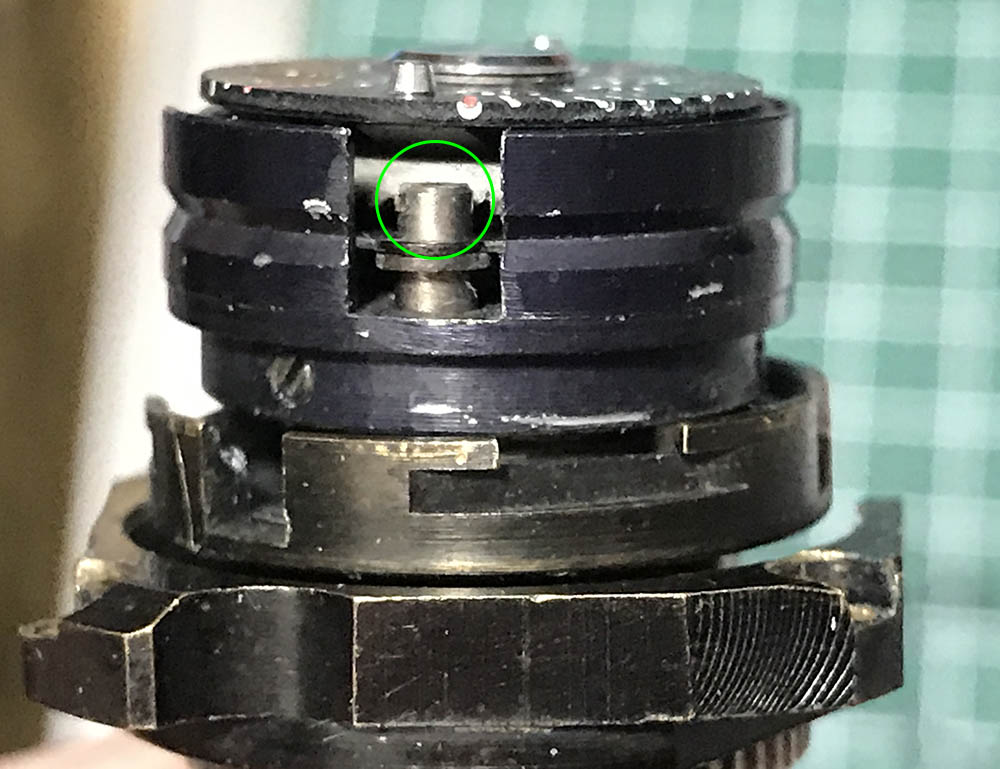
Carefully un-solder this part so you can remove the speed selector assembly completely.
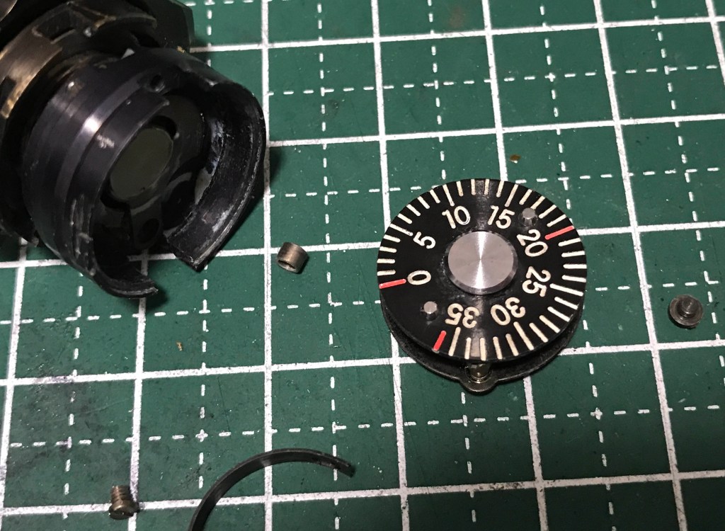
Carefully clean everything here, do not leave any residues. Grease the A/R assembly lightly after cleaning it and assemble it back properly. Clean the film-counter mechanism very well, you may want to unravel the spring to make things even cleaner. Winding the advance-lever spring can be a pain but that has to be done. Oil or grease anything that needs it so the advance-lever mechanism is smooth, the same goes for the film-counter mechanism.
Leave the speed-selector assembly for now, you will have to disassemble it further in order to properly clean it. It’s a very delicate assembly so do not damage anything while you handle it.
We’ll discuss how to clean the rangefinder mechanism in a later article, it’s a very delicate and precise assembly so you’ll want to clean it the right way.
Conclusion:
That’s all for the upper mechanisms. It is the most complicated part of the camera, most of the important mechanisms are housed here. You’re going to spend the most time adjusting the mechanisms here after cleaning them and I would even spend a few nights here just to be sure I got things right. We’ll discuss how to clean or adjust the mechanisms here in later articles, it won’t be enough to condense everything in a single post since there are lots of small details that had to be discussed properly.
For easy navigation, here are the links to the other parts:
I advise that you read them all in-order so you’ll follow everything better.
Thank you all for supporting and following my work. I try to give you what you won’t normally find elsewhere. If you enjoyed this article, please share this with your friends. If you think that this was helpful and you want to see this blog continue to help other people, consider supporting this. Your help helps me offset the cost of maintenance and hosting this site. You help me a lot by helping me purchase, develop and scan film for my reviews. See you again in the next article, Ric.
Help Support this Blog:
Maintaining this blog requires money to operate. If you think that this site has helped you or you want to show your support by helping with the site’s upkeep, you can make a small donation to my paypal.com (richardHaw888@gmail.com). Money is not my prime motivation for this blog and I believe that I have enough to run this but you can help me make this site (and the companion facebook page) grow.
Leave me some tip?
Thank you very much for your continued support!
$2.00
Helping support this site will ensure that this will be kept going as long as I have the time and energy for this. I would appreciate it if you just leave out your name or details like your country’s name or other information so that the donations will totally be anonymous. This is a labor of love and I intend to keep it that way for as long as I can. Ric.

Mar 06, 2023 @ 23:57:21
Hello,
I’ve been watching the stripdown and repair of Nikon sp you have generously distributed on the youtube channel. I must have went over it at least a dozen times, and had a question if you can find time in your busy schedule to answer me one day via e mail. I am and consider myself a fairly good camera repair man ( non proffesional) and have worked on a lot of cameras, but mostly lenses. I have acquired a minty Nikon sp, but the small 28-35 peep window is dusty to view through. Does the top need to be taken off or can I go through the front. I feel I can handle the removal as I have been in the front and cleaned outer windows. I am a little nervous and hesitant to try to clean this finder. What’s your opinion. Is there another way to do this? I don’t want to pay $300-to $500. for this repair.
Thanks very much.
Paul Conway